In this post will be shown an electromechanical component called relay. Will be shown how it works and some project examples.
How it works?
The working principle is very simple. An electromagnet receives electric current and produces a magnetic field, which attracts a metallic piece connected to mobile contact, making the switching, which can open or close a circuit.

Some relays have a spring which makes the mobile contact return to the original position, when there is no more current passing by the coil.

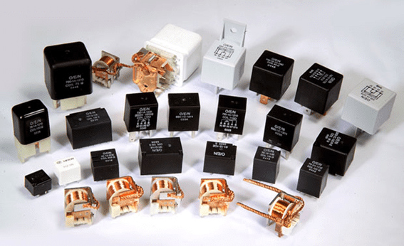
Exist electromechanical relays of many sizes, poles and power levels, but the working principle is the same.
Relay control by light project
This is a circuit project which controls a relay with a LDR sensor, let’s use circuit polarization techniques.

To know more about polarization techniques, click in the button below to read the first part of transistor polarization.
BJT polarization (Part 1)Click here
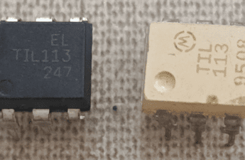
The chosen transistor is the TIP122, looking at datasheet, the gain (h_{FE}) and the collector-emitter voltage in saturation (V_{CE(SAT)}) are respectively 1000 and 2V.
The current to activate the relay must be at least 26.7mA, the relay’s coil resistance is 180Ω. Therefore, the base current I_{B} must be.
I_{B}=\frac{I_{C}}{h_{FE}}=\frac{26.7m}{1000}=26.7\mu A
The chosen supply voltage is 9V, the relay is the ML2RC1 6V type, whose diagram can be found here. Therefore, the voltage emitter must be 1V and the collector voltage 3V. To the transistor operates in saturation, the base voltage must be bigger than the collector and emitter voltages. Calculating RE, the emitter resistor.
I_{E}=I_{B}+I_{C}=26.7\mu +26.7m=26.726m A
RE=\frac{V_{E}}{I_{E}}=\frac{1}{26.726m}=37.4\Omega
I used the commercial value closest available, which is 47Ω. Calculating RB resistor, let’s considerate that the LDR must pass by 13kΩ to enter in saturation.

The base voltage was chosen as 4V, calculating the current passing through LDR.
I=\frac{V_{cc}-V_{B}}{R_{LDR}}=\frac{9-4}{13k}=0.384mA
Let’s call I_{BB} the current which pass through resistor RB.
I_{BB}=I-I_{B}=384\mu -26.7\mu =357.3\mu A
R_{B}=\frac{V_{B}}{I_{BB}}=\frac{4}{0.3573m}=11.2k\Omega
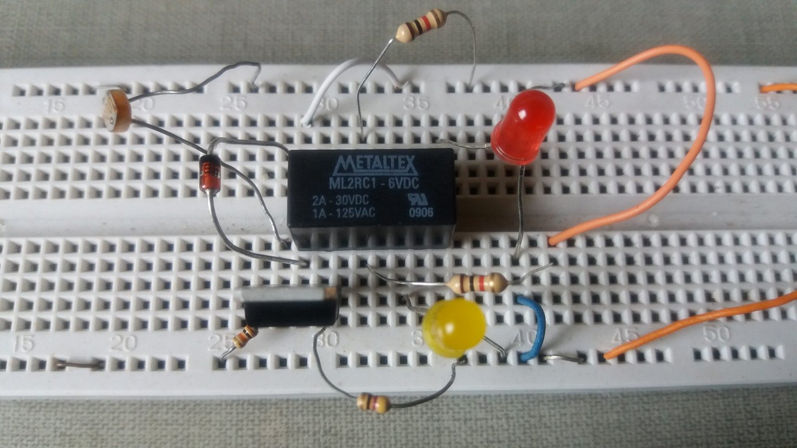
Was used the commercial value of 10kΩ to RB. This is the circuit in protoboard.
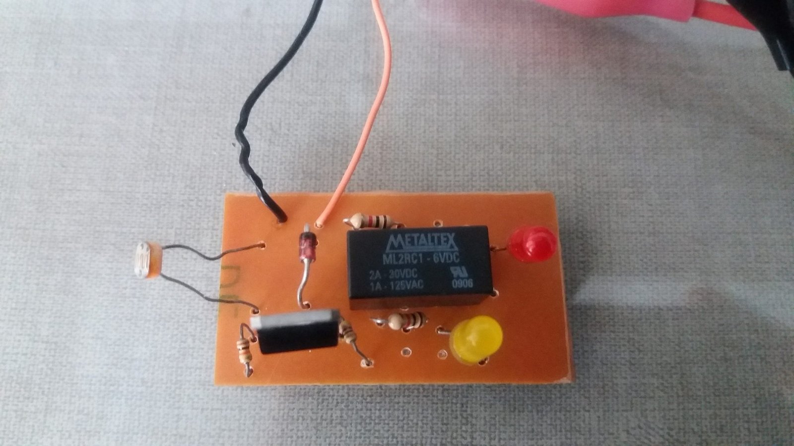
Mounted in printed circuit board, the LEDs serve to show the relay’s switching.
Diode’s function
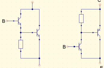
What the zener diode is doing in the circuit below? The inductor or coil accumulates energy, when the transistor changes to cut mode, the relay produces a peak voltage which can damage the circuit. The diode makes that the voltage in the coil is 0.7V, can use also a common diode.
Emitting sounds with relay
This circuit makes the relay emit sound by switching. Each pressed button emits a sound in a frequency. Coils and capacitors are energy accumulators, the energy exchange between them make the relay switch in a frequency which depends on the capacitor value and coil`s resistance. The relay also will emit a sound if no button is pressed.