Today is shown how to do RL circuit analysis which have resistors, switches and inductors.
Charge an discharge phases in RL circuit
Was built this circuit below in Qucs simulator to show charge and discharge phases. V1 source simulates a square wave DC power source with a period of 200 μs. The first 100 μs are charging phase and other half of time is discharge phase.
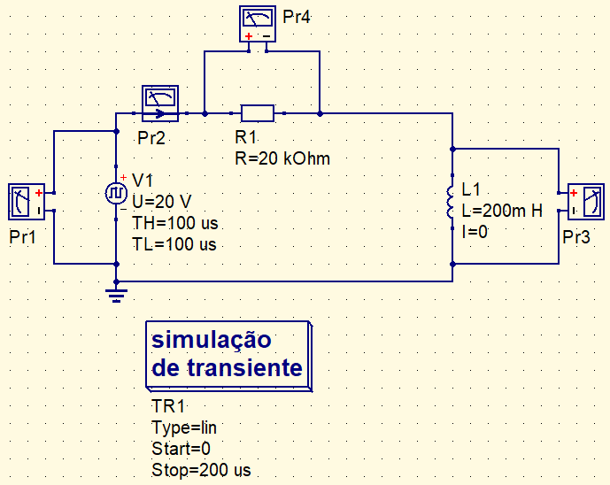
Executing simulation, we have the following graphics.

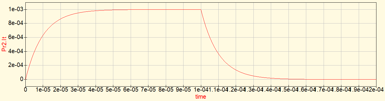


In RL circuit, time constant is calculated dividing inductance by resistance. In this circuit, period is 10 μs.
\tau =\frac{L}{R}
Charging phase’s equations
In the transitory charge period, coil current follows the equation below.
i(t)=\frac{U}{R1}(1-e^{\frac{-t}{\tau }})
This is equation of voltage in coil.
v_{L}(t)=U\cdot e^{\frac{-t}{\tau }}
Voltage in resistor.
v_{R}(t)=U\cdot(1-e^{\frac{-t}{\tau }})
In circuit above, equation are in this way.
i(t)=1m\cdot(1-e^{\frac{-t}{10\mu }})[A]
v_{L}(t)=20\cdot e^{\frac{-t}{10\mu}}[V]
v_{R}(t)=20\cdot (1-e^{\frac{-t}{10\mu }})[V]
Discharge phase’s equations
Equations of current and voltage in coils during discharge phase.
i(t)=\frac{U}{R1}\cdot e^{\frac{-t}{\tau}}
v_{L}(t)=V_{L}\cdot e^{\frac{-t}{\tau}}
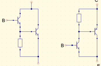
V_{L} is the sum of all voltages in resistors in same loop of coil and have inverted polarity. Let’s use this circuit as example.
The S1 switch is closed, while the coil is charging. S1 will open in 10 μs and L1 coil will be discharged. This is the simulation of coil voltage, red curve in following graphic, showing when S1 is open.

In this circuit, V_{L} is calculated this way.
V_{L}=-(V_{R1}+V_{R2})
V_{R1} and V_{R2} are 10.38 V e 51.9 V respectively. Therefore V_{L} is -62,28 V. Voltage discharge equation is:v_{L}(t)=-62,28\cdot e^{\frac{-t}{0,833\mu }}[V]
Initial values
In some problems coils have a initial current I_{i}. This value can be determined calculating current which pass through coil and considering the later as a short-circuit, or is given by problem itself. The equation is:
i_{L}(t)=I_{f}+(I_{i}-I_{f})e^{\frac{-t}{\tau}}
I_{f} is current of stationary state after transition. It is considered that RC and RL circuits obtain stationary state after 5 time constants.Thévenin theorem application
How to analyze a more complex RL circuit? It is necessary to apply Thévenin theorem to find equivalents voltage and resistance in coil terminals. The procedure have already been explained in post “Theorems of superposition, Thévenin and Norton”, whose link is in the button below.
Applying Thévenin theorem, becomes much easier analyze a more complex RL circuit.

Calculating time constant.
\tau =\frac{L}{R_{Th}}
Instant values
Formula demonstration to calculate instant value of current in a coil.
i_{L}=I_{F}+(I_{i}-I_{f})e^{\frac{-t}{\tau}}
i_{L}-I_{F}=(I_{i}-I_{f})e^{\frac{-t}{\tau}}
e^{\frac{-t}{\tau}}=\frac{i_{L}-I_{f}}{I_{i}-I_{f}}
e^{\frac{t}{\tau}}=\frac{I_{i}-I_{f}}{i_{L}-I_{f}}
Applying Neperian logarithm in both sides.
ln(e^{\frac{t}{\tau }})=ln(\frac{I_{i}-I_{f}}{i_{L}-I_{f}})
\frac{t}{\tau }=ln(\frac{I_{i}-I_{f}}{i_{L}-I_{f}})
t=\tau ln(\frac{I_{i}-I_{f}}{i_{L}-I_{f}})
To calculate instant value of voltage in coil.
v_{L}=V_{i}e^{\frac{-t}{\tau }}
t=\tau \cdot ln{\frac{V_{i}}{v_{L}}}
Formula of stored energy in a coil
W=\frac{1}{2}LI_{m}
W is stored energy and I_{m} is current in permanent state after coil’s charging.