
This is the post’s second edition. Additional information has been added.
This post’s subject is the 4093, it is an integrated circuit very simple and useful to build many electronic projects.
How it works?
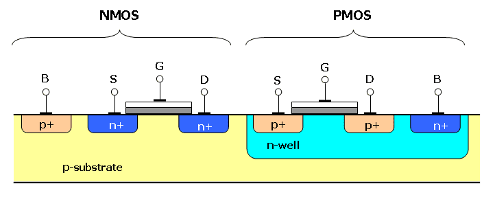
The 4093 is a CMOS, a family of integrated circuits which have field effect transistors with a silicon oxide layer (in grey) and another with polysilicon (in white) in the transistor’s gate (G). Below are field effect transistors MOSFETs in cross-section.
Inside 4093, there are 4 NAND logic gates with Schmitt Trigger, can be supplied with voltages from 3 to 15 V. Reminding that VSS is the ground or GND.

To see how the logic gate NAND works, click in the button below, will go to a post about combinational circuits.
Combinational circuitsClick here
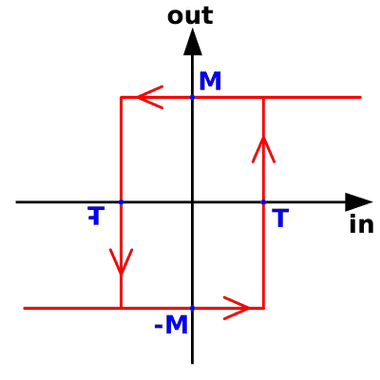
What is Schmitt Trigger? It is a comparator circuit which serves to eliminate noises. When the input is above a determined value T, the output will be level high M or “1”, when stays below a certain value -T, the output will be low level -M or “0”.
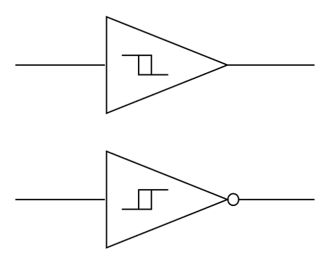
These are the Schmitt Trigger’s symbols, the above is the inverter and below is non-inverter.
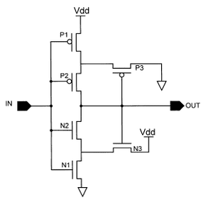
This is the Schmitt Trigger’s circuit inside a chip, the input is linked to the NAND gate’s output. The Ps are the PMOS transistors and the Ns are NMOS.
Some applications
It is possible to build many circuit projects with this chip. This post only shows few applications.
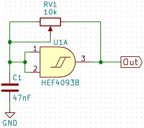
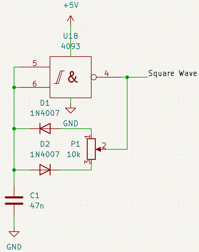
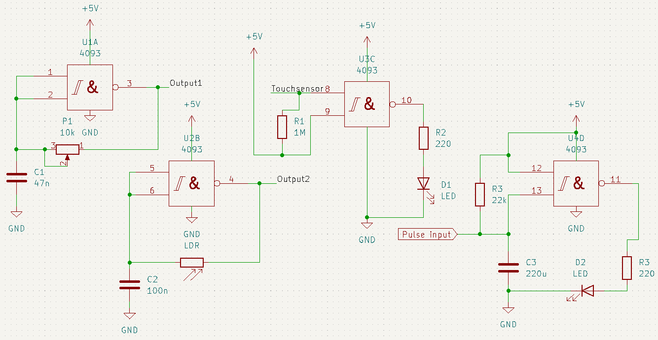
- Square wave generator: This circuit produce a square wave. Can put a resistor instead a potentiometer, which serves to control a frequency band. Can change the values of capacitor and potentiometer, or resistor, to get a different frequency.
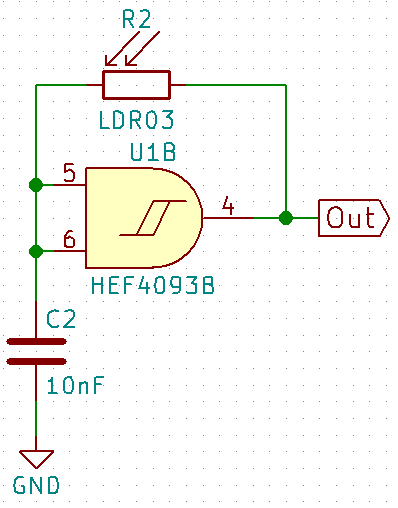
- Light sensor: Just replace the resistor with a LDR and there is an oscillator whose frequency is controlled by light intensity.
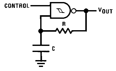
This is the frequency equation of this oscillator type.
f=\frac{1}{RCln(\frac{V_{T}^{+}(V_{S}-V_{T}^{-})}{V_{T}^{-}(V_{S}-V_{T}^{+})})}
V_{S} is the output voltage value, in this case has the same value of supply voltage V_{CC}. V_{T}^{+} is the positive limit which generates the high level in output and V_{T}^{-} is the negative limit which produces low level. The difference between V_{T}^{+} and V_{T}^{-} is the hysteresis voltage V_{H}. In 4093’s datasheet, these values are shown and depends on the temperature and voltage supply.
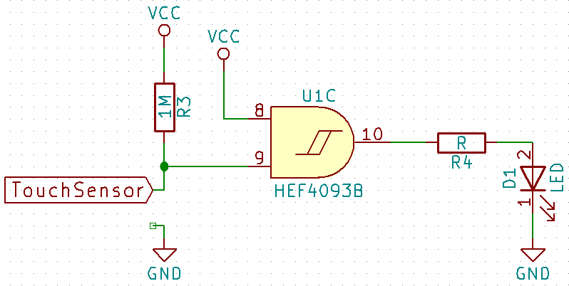
- Touch sensor: When touch in the sensor, can be a metallic part or a bare wire, a LED is turned on.
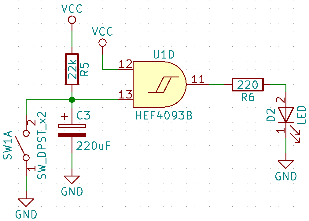
- Monostable: When the switch SW1A is closed, the LED is turned on. When it is opened again, the LED stays turned on for a while. When higher the C3 and R5 values, longer will be the time the LED is turned on.
Project example
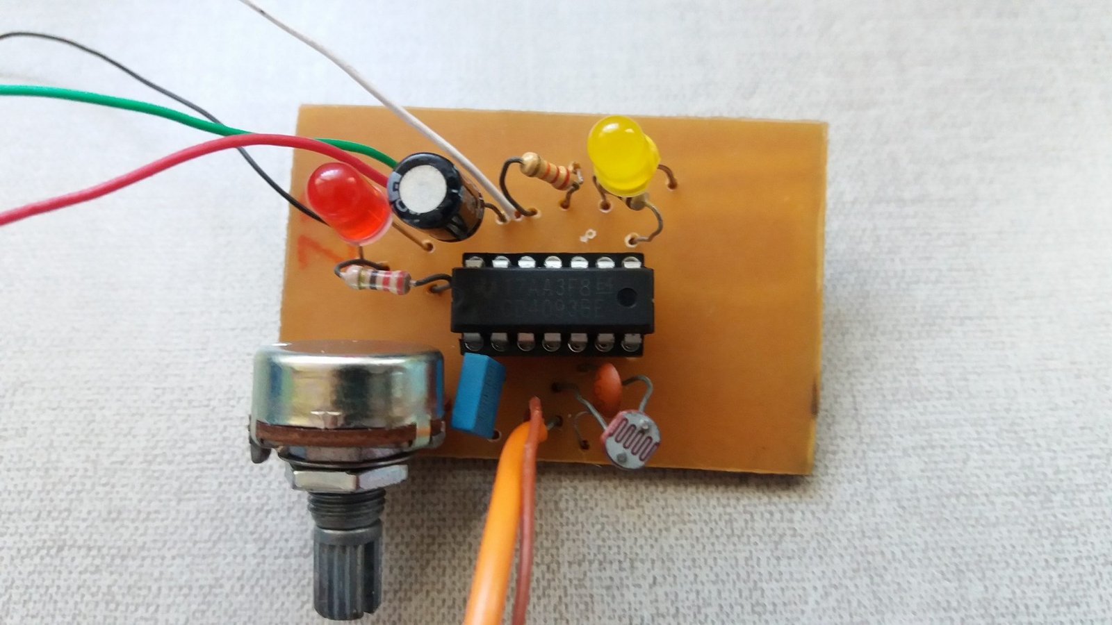
Component list:
- Wires.
- Printed circuit board.
- CD4093.
- 10 kΩ potentiometer.
- LDR.
- 47 nF polyester capacitor.
- 100 nF ceramic capacitor.
- 2 LEDs of any color.
- 220 μF electrolytic capacitor.
- Resistors: 2 of 220 Ω, 1 of MΩ and 1 of 22 kΩ.
