
This is the second part of photovoltaic solar panels topic.
Solar panel positioning
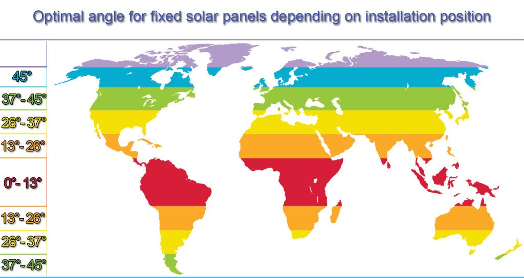
To obtain maximum energy production, the photovoltaic module must be positioned considering Earth’s rotation inclination axis, latitude, and Sun’s azimuthal angle. To receive maximum energy daily, the module must always be appointed to geographic north and the inclination angle must be adjusted in relation to the soil.
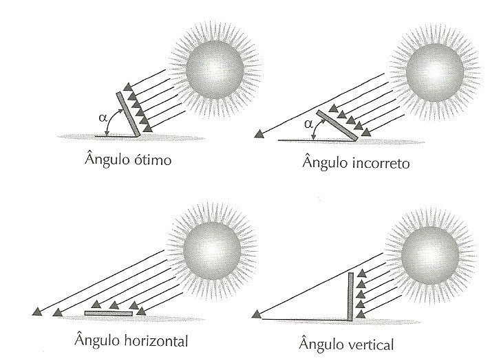
Inclination angle depends on the altitude.
Considerate the solar panel model:
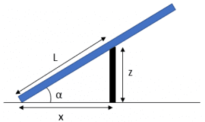
The equation to calculate height stem z:
z=L\cdot sen\alpha
To calculate the distance x:
x=L\cdot cos\alpha
To build solar panels parallel rows, it is necessary leave a distance d between the rows which is calculated in the following way:
d=3,5\cdot z
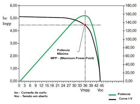
Characteristic curve
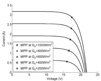
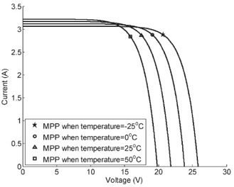
Here are the examples of characteristic curves of a solar panel. The black curve is the current-tension (I-V) characteristic curve and the green curve is the power-tension curve (P-V). Note the red dot which is the Maximum Power Point. All solar panels follow this pattern curve. Usually, these curves are provided by the manufacturer.
Temperature and solar radiation also influence the curve. Influence by solar radiation:
Influence by temperature:
Materials for photovoltaic cells
There are various materials to build photovoltaic modules, usually, the material is silicon, however, there are various types of silicon and other materials.
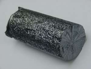
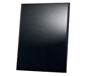
- Monocrystalline silicon
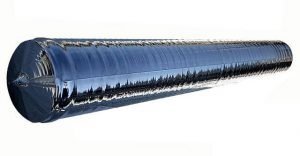
The monocrystalline silicon has a homogeneous molecular structure, here is the final product of monocrystalline cell.
Those types of cells are the most efficient actually, but have a high cost and need to be installed in modules to obtain mechanical resistance. The manufacturing process waste big parts of silicon.
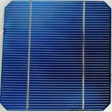
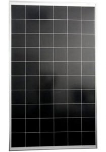
- Polycrystalline silicon
This silicon type has many crystals with different shapes and sizes in the molecular structure. Here is a solar cell made with this material.
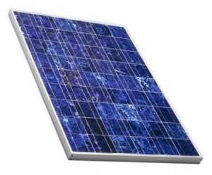
The manufacturing cost of this material is lower and produces less silicon waste, but efficiency is a bit lower compared with monocrystalline due to low purity. Also needs to be installed in modules for mechanical protection.
- Thin film formless silicon
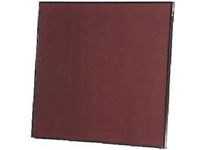
Used more for small applications, cells with this material have low efficiency. Its efficiency decrease in 6 or 12 months due to degradation caused by light until reaches a stable value. The efficiency can be increased with stacking, a technique to put many formless silicon layers, however, the technique’s cost is high.
- Thin film of cadmium telluride (CdTe)
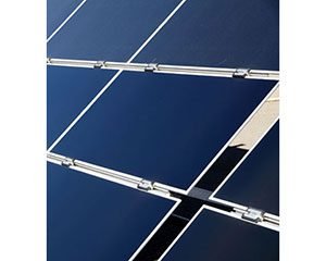
Cells with this material have the best cost/efficiency ratio between the thin film panel, are used in large solar power plants. It is not produced on a large scale because cadmium is toxic and tellurium is a rare material.
- Thin film of copper selenite, indium and gallium (GICS)
It has the highest efficiency between the thin film solar cells, however, are still very expensive.
- Hybrid cells
It was searched to combine the high efficiency of crystalline cells with the thin film’s lower cost. There is no efficiency degradation due to light and works well with high temperatures.
Efficiency table
Here is a table to compare efficiency between cells and modules for different materials.
| Material | Efficiency cell in laboratory | Commercial cell efficiency | Commercial module efficiency |
| Si monocrystalline | 24,7% | 18% | 14% |
| Si polycrystalline | 19,8% | 15% | 13% |
| Si formless | 13% | 10,5% | 7,5% |
| CdTe | 16,4% | 10% | 9% |
| GICS | 18,8% | 14% | 10% |
| Hybrid | 20,1% | 17,3% | 15,2% |
