
In this post I will explain what are flip-flops. Are memory digital or sequential circuits whose output depends of the input and the output`s actual state.
Latches
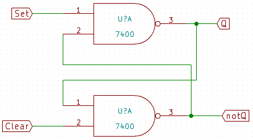
Are digital circuits with logic door NAND or NOR, where a logic door`s output is linked to another logic door`s input. This type of circuit can store one bit of information. This is a NAND latch.
This circuit`s truth table.
 This is the NOR latch.

And your truth table.

Clocks
Flip-flops need a square wave generator circuit called clock to work, an astable 555 can be a clock, click in the button below to know how to build one.
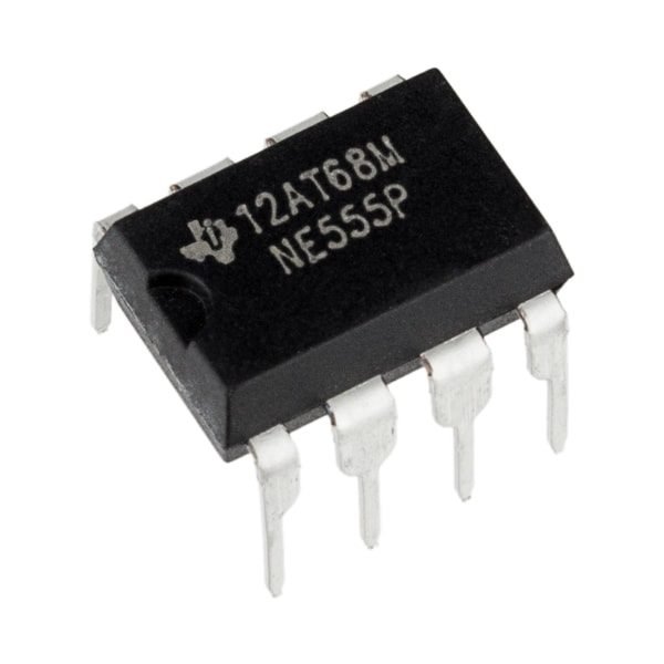 555Click here
One alternative is the astable circuit with 7414.

Other alternative is an astable with two transistors.
![]()
Types of flip-flop
This is the SR flip-flop.

In this circuit, the Q only change state when happen a positive transition of clock, by that, change from 0 (low level) state to 1 (high level) state or a negative transition (from level 1 to 0). Here is the truth table considering clock transitions.
The circuit below is the JK flip-flop.
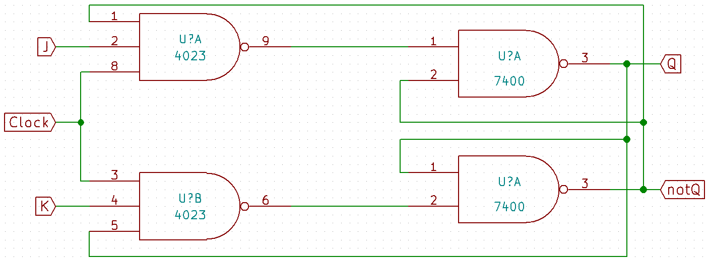
In this circuit, there is no invalid response in any input condition. Note that the NAND doors have 3 inputs. Below we have the truth table considering clock transitions.

The T flip-flop is a simplification of the JK, just link the J and K input. The truth table is also simplified.


This is the D flip-flop, the clock input can serve as an enabler. The D input only influence in the output with a positive or negativa clock transition.

Here is this circuit’s truth table.
 Integrated circuits with flip-flop
Some integrated circuits to use flip-flop in practice.
- 74LS112 has 2 JK flip-flops;
- 74LS175 has 4 D flip-flops;
- CD4043 has 3 NOR latches and 3 NAND latches.
Exist many others integrated circuits with flip-flops and latches. The chips have terminals CLR (clear) and PR (preset), which are asynchronous inputs which can the flip-flop`s output independent of the clock and the synchronous inputs (J, K, S, R, D and T).
