I received requests to write about two types of universal motor: conductively and inductively compensated. This post can be considered as the second part of universal motor operation.
Post about universal motorClick here
Purpose of compensating winding
In an electric motor, armature winding are rotor’s wires. When motor is on, electric current which pass through conductor wires in rotor produces a magnetic field. This generated field is the armature reaction, it weakens and distorts stator’s magnetic field.

If stator’s magnetic field get weaker, the motor loses torque. Because torque \vec{\tau} on a coil turn is directly proportional to magnetic flux density \vec{B}. \vec{\mu} is magnetic dipole moment and N is number of turns.
\vec{\tau}=N\vec{\mu }\times \vec{B}
The universal motor uses compensating winding to reduce armature reaction. \times is vector multiplication, it’s different from escalar multiplication between two numbers.
Conductive compensation
In this configuration, compensating winding is connected in series with main and armature winding. In addition to receive current directly from power supply.

Magnetic field of compensating winding (C) is put in slots of main poles of stator (S), it’s involve the rotor (R) and almost cancel armature reaction field. (F) and (A) are field and armature winding respectively.

About speed control, universal motor has the same feature of DC series motor, too high speed when there is no load. A rheostat (variable resistor) in series or electronic circuits are used to have a bigger speed control range.
Inductively compensation
In this configuration, compensating winding is short-circuited.

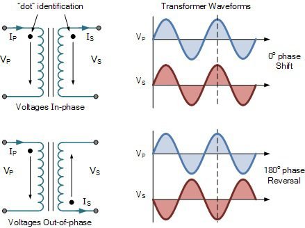
Armature winding acts as primary of a transformer, while compensator is the secondary which receives magnetic field generated in rotor. Why compensating is winding in short-circuit? When it receives armature’s magnetic flux, receives an induced voltage, in short-circuit, there is current circulation. Compensating winding’s magnetic field is in opposite polarity to armature winding. The result is that both fields are in opposite phases and cancel each other.