
This post’s subject is PID controller. It is a controller to feedback systems, not only is used in robotics, but also in many industrial processes.
Feedback system
In a feedback system there is a process being controlled, a sensor sends signals to the controller. The controller makes some adjustments in the process to the sensor send the desired signals.

Setpoint (SP) is the desirable output value that the process variable (PV) must reach. If SP is equal to PV, the controller does not need to act in the process. If SP is different than PV, the controller acts in the process until the sensor tell that PV is already equal to SP. An example can be an air conditioning or heater in a room, whose SP is temperature the person put, the controller is the air conditioning or heater, the sensor measure the temperature and the process is the room.
What is PID?
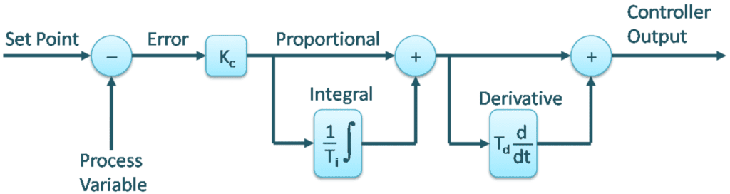
PID means Proportional, Integral and Derivative respectively, each one of three is a control block. Don’t need to use always all the three, can also use the P, PI or PD.

The difference between SP and PV is called error. Each one of the control blocks receive the error represent by e(t) and multiply by gain K. In P, the gain is K_{p} and the output is:
K_{p}\cdot e(t)
The outputs in I and D respectively:
K_{i}\int_{0}^{\tau}e(\tau)d\tau
K_{d}\cdot \frac{\mathrm{d} e(t)}{\mathrm{d} t}
All output in blocks are added. \int_{0}^{\tau} means an integer in a time range \tau and \frac{\mathrm{d} }{\mathrm{d} t} is the derivative of function. Integer and derivative are advanced calculations which I won’t go deeper in this post. The gain of control blocks can be adjusted. If the gain values are too low, it will take too long to reach the setpoint (red curve in the graphic). By other side, with gains too high, the signal can reach fast the setpoint, but will generate undesirable oscillation (black curve).

The undesirable oscillation is called overshoot. The values of gain to obtain the desired response depends of the controller and the process.
Controllers PID algorithms
The PID controller can have three algorithms: interactive, non-interactive and parallel. The interactive or series is the oldest.
K_{c}\cdot \left [ e(t)+\frac{1}{T}\int e(t)dt \right ]\cdot \left [1+T_{d}\frac{\mathrm{d} }{\mathrm{d} t} \right ]
This is the non-interactive algorithm, if the block D is deactivated (Td=0), it works just like the interactive without D.

K_{c}\left [ e(t)+\frac{1}{T_{i}}\int e(t)dt +T_d \frac{\mathrm{d} e(t)}{\mathrm{d} t}\right ]
The parallel algorithm, hasn`t a gain control which affect all the three blocks and each block has a gain.

K_{p}\cdot e(t)+K_{i}\int e(t)dt+K_{d}\frac{\mathrm{d} e(t)}{\mathrm{d} t}
Application in robotics
How to use the PID controller in robots? If a robot control system have feedback (closed loop), you can implement a PID controller. An example is an encoder, sensor which measure the speed of motors, send data to a controller to control the speed motors with PWM. A robot which self-balance in 2 wheels can have a PID controller.

