
Antennas convert electric signals into electromagnetic waves and vice versa in an efficient way. this post will be shown an introduction to antennas, parameters, and some types of antennas.
How do they work?
Antennas are made of conductor materials, which receive alternate current signals. These signals produce electromagnetic waves which spread through the air. Also can receive electromagnetic waves and convert them into an electric signal.

Antenna parameters
Every antenna has features that determine how will transmit and receive electromagnetic waves.
- Polarization: Determine the electric field plane’s position, an antenna with conductors in vertical will produce waves in vertical polarization.

A wave with horizontal polarization is produced by antennas positioned horizontal, these animations only show the electric field. Other polarizations derive from these two.

- Radiation diagram: Graphical representation which shows how the antenna spreads electromagnetic waves in horizontal (H) and vertical (E) planes. The lobules represent the power distribution.

- Gain: Although the antennas are passive components, they have gain. Represent the antenna capacity to receive signal, comparing with a reference antenna. The formula of gain in dBi is:
G(dBi)=10log(\frac{P}{P_{r}})
P is the antenna’s radiation power and P_{r} is the radiation power of a reference antenna. Usually, an isotropic antenna, which irradiates to all sides, is used as a reference.
- Directivity: Is the maximum value of directive gain, by that, the capacity to concentrate power in one direction. It is calculated by the ratio between the maximum radiation intensity (U_{max}) and average radiation intensity (U_{av}).
D=\frac{U_{max}}{U_{med}}
- Bandwidth: Every antenna has an operating frequency band determined by the bandwidth. Depends on polarization and input impedance which changes with frequency. The frequency where has the lowest impedance is called resonance frequency. I will enter more details about the impedance of antennas in another post.
- Radiation resistance R_{ir}: To the signal generator, the antenna is like an ideal resistive load, which radiates electromagnetic waves instead of heat. When bigger this resistance, the greater is the radiated power in free space.
Some types of antennas
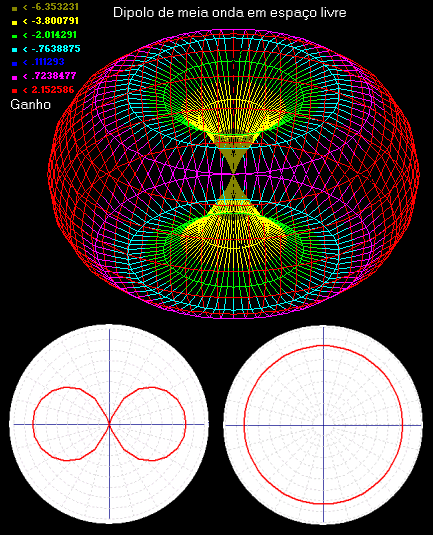
The dipole antenna has two conductors pointed in opposite directions, the total length of conductors is equal the half of wavelength \lambda, in which this antenna operates. For that, it is called half-wave dipole.
[WPGP gif_id=”8838″ width=”600″]
The radiation diagram and an example of dipole antenna respectively. The radiation resistance is 73Ω.

The one-quarter wave monopole antenna is half of a dipole in a conductor plane. The antenna length is one-quarter of wavelength.


This is a radiation diagram of this type of antenna in the vertical plane. The radiation resistance is 36.5Ω.

In the small loop antenna, the ring dimensions are much smaller than the wavelength.

The radiation resistance is calculated in this way.
R_{ir}=\frac{320\pi ^{4}S^{2}}{\lambda ^{4}}
In the next part, I will talk about many other types of antenna and other parameters.

[…] DMA’s irradiation diagram. According to the news, software in FPGA can control the antenna’s electromagnetic […]