
In this post will be shown how it is possible to produce high voltages only with diodes and capacitors. These circuits are the voltage multipliers.
Doubling the voltage
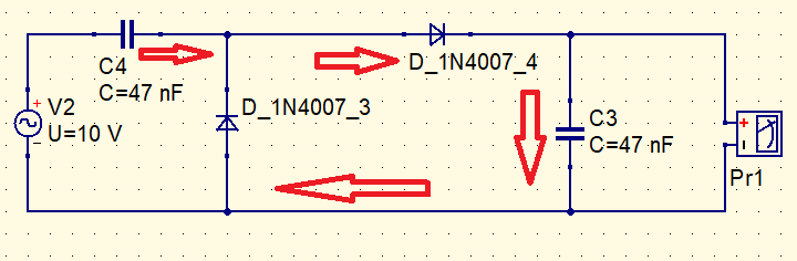
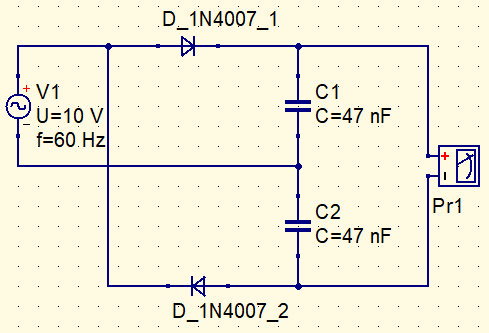
Voltage multipliers convert alternate voltage in direct, whose value is the double of input peak value. This circuit is the half wave doubler voltage.

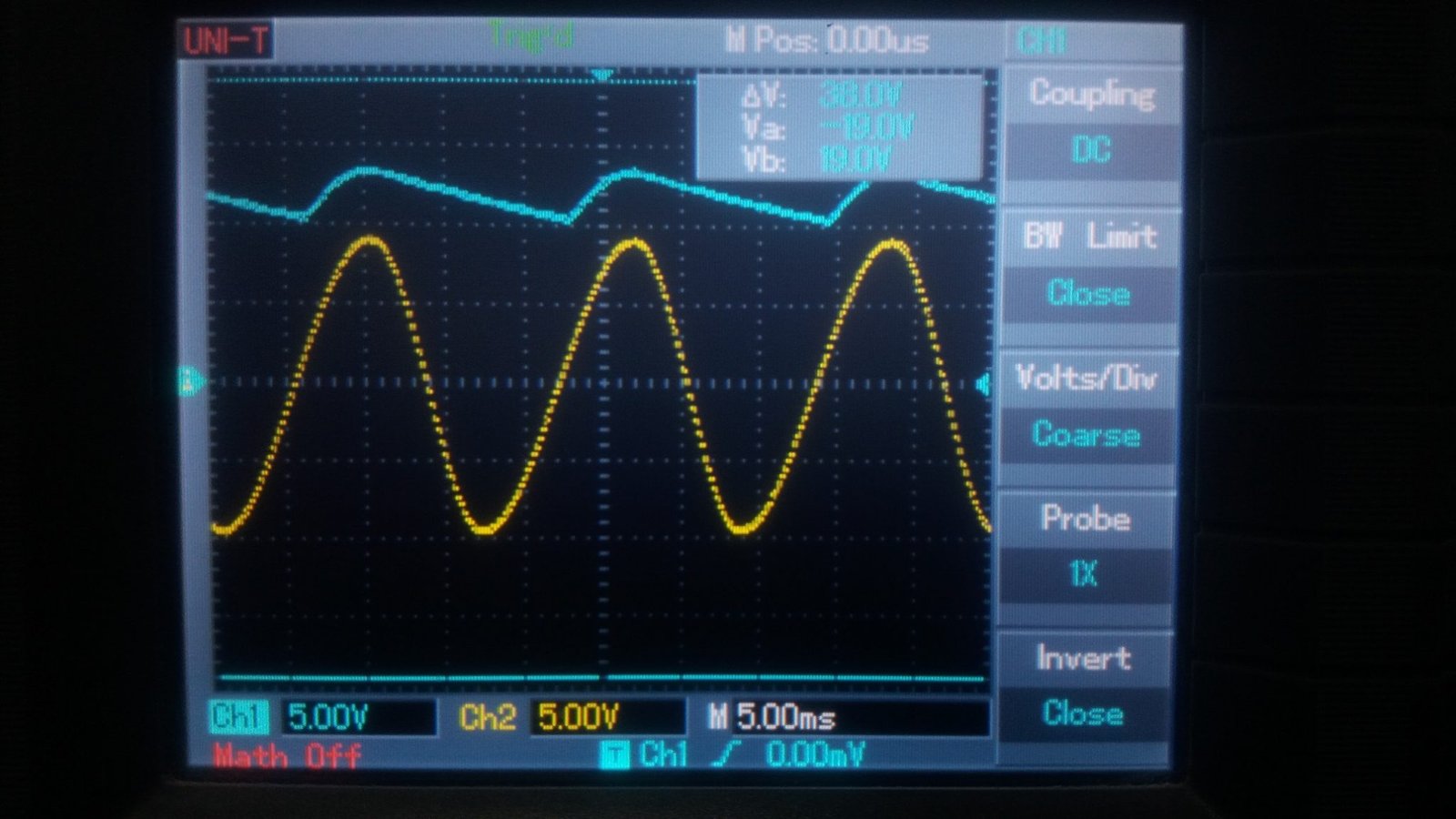
The yellow curve (Ch2) is the input signal produced by function generator and the blue signal (Ch1) is output. The oscilloscope’s probe reduce a little the output voltage.
Inverting polarity of diodes, is obtained a negative DC voltage.


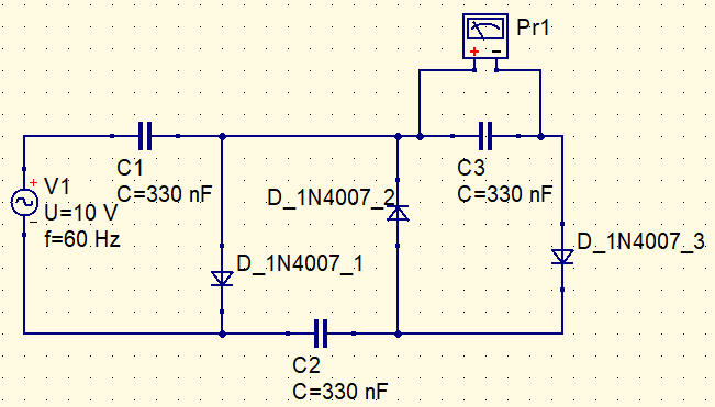
How this circuit works? When the input is negative, the capacitor C4 is charged until the voltage U-0.7V.
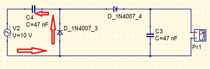
V_{C4}=U-0,7
When the AC input is positive, the C4 capacitor is discharged and the C3 capacitor is charged.
Summing mesh voltages, we have:
U=-V_{C4}+0,7+V_{C3}
U=-U+0,7+0,7+V_{C3}
V_{C3}=2U-1,4
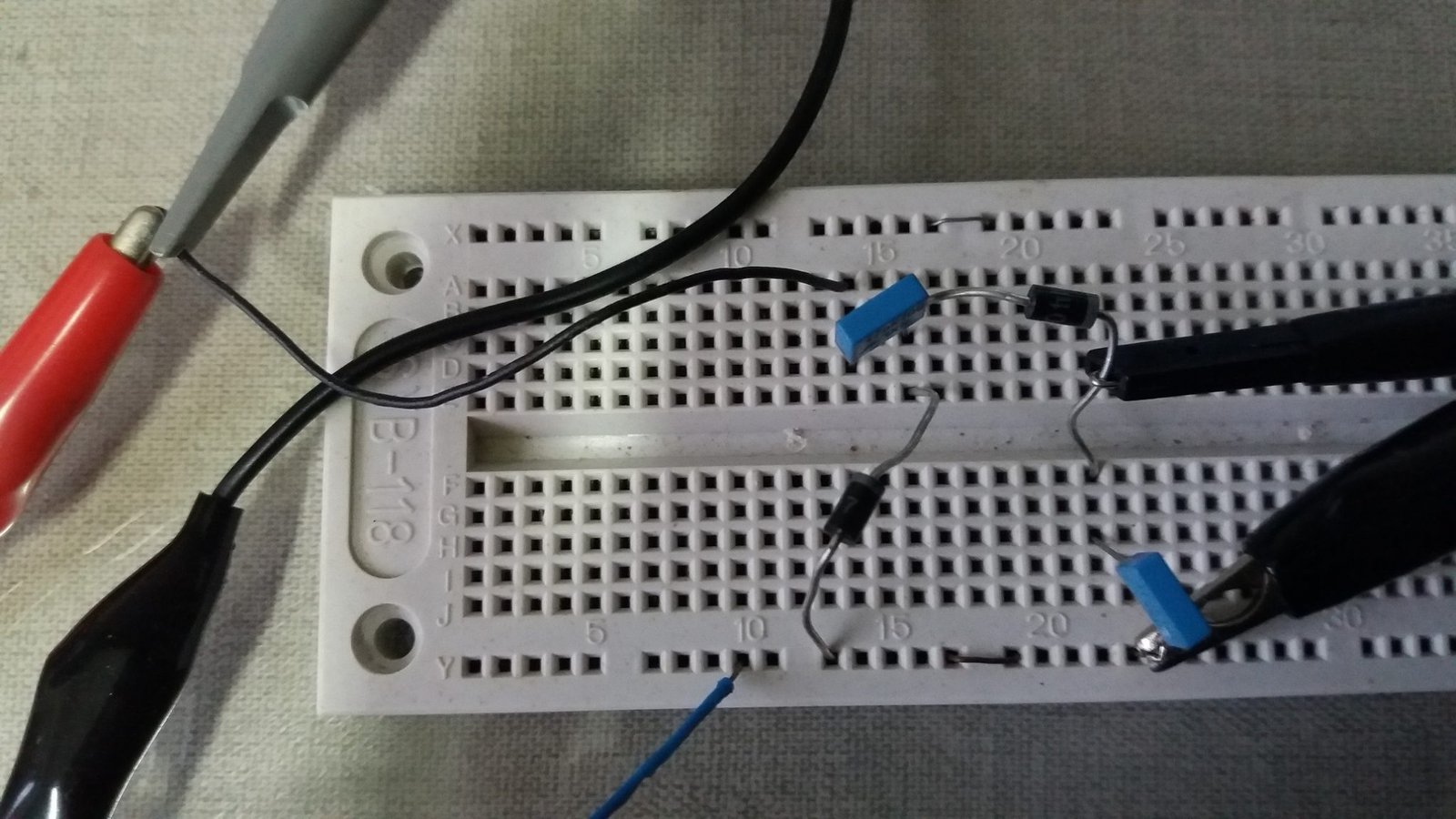
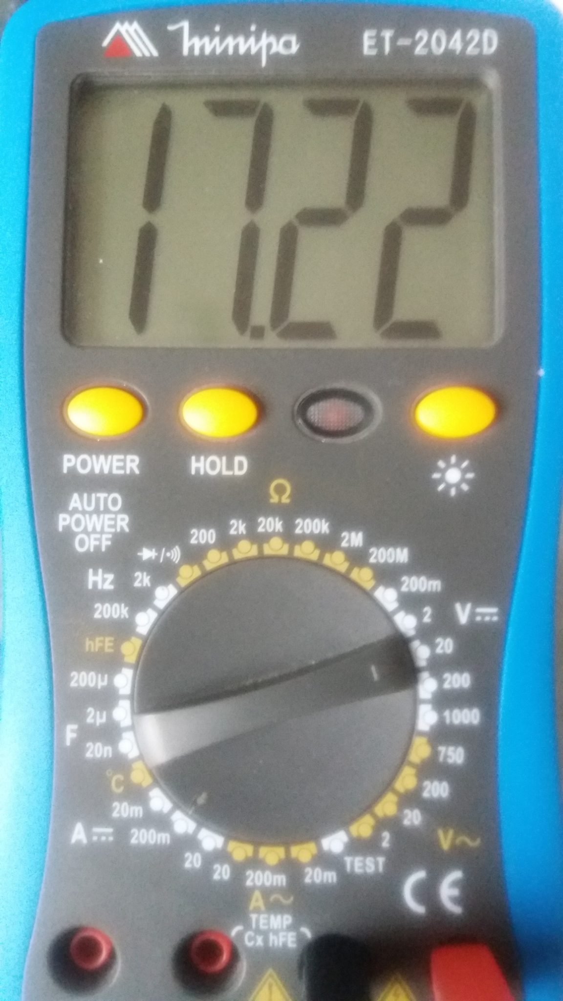
When the input changes direction again, C4 is charged and C3 is kept in the current state. Unless there is a load in parallel with C3, in this case, it will be discharged. The measure in the circuit’s output is shown below.
Why isn’t the output signal a straight line? If measure in oscilloscope the node between C4 and diodes, will see the input signal moved up. The AC signal is in 60 Hz.
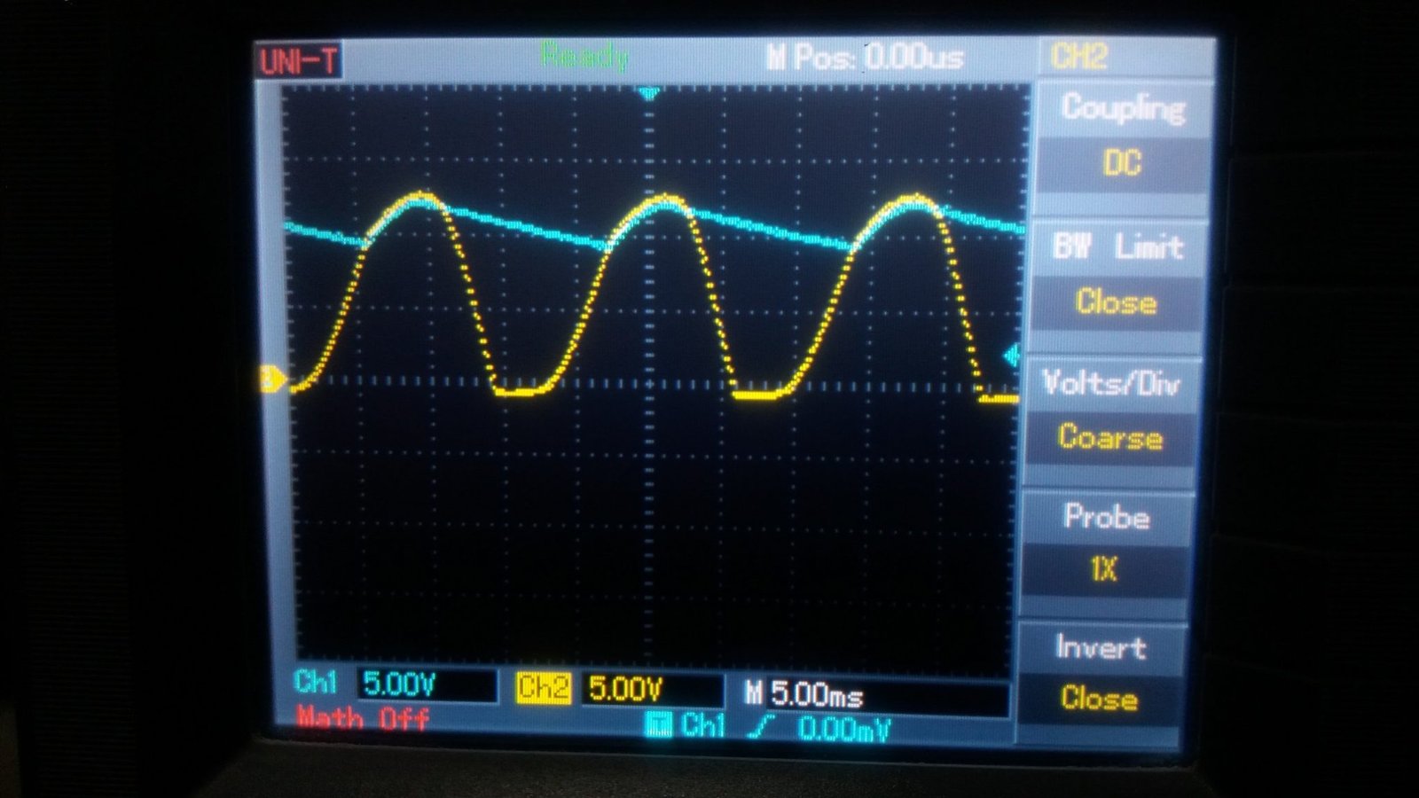
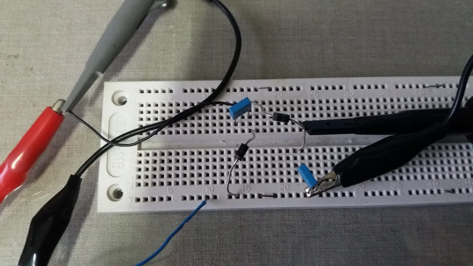
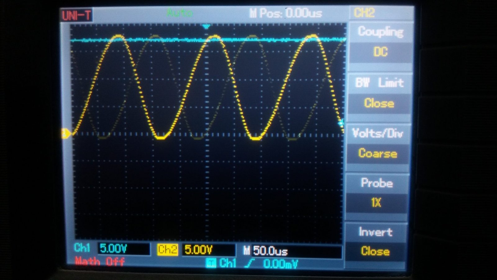
This signal was “clamped” by C4 and D_1N4007_3. D_1N4007_4 rectify the signal and C3 does not discharge much producing the Ch1 signal. Increasing the frequency, output signal stays as a straight line, below show the input and output with frequency of 5730 Hz.
Others voltage doubler
The exhibited circuits above are cascading doublers. This is the full wave circuit doubler.

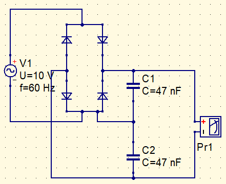
This is the doubler in bridge, makes a full wave rectification with a diode bridge. Both circuits have the same function and produce the same result.

Increasing the voltage
Adding more capacitors and diodes, can create voltage multipliers by other numbers. However, when higher the voltage, lower the provided current. This is the voltage triplifier with it DC value in the output.

This is the voltage quadruplier.

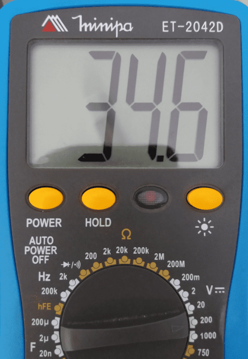
This circuit can generate more than 1,000 V from power plug.
Warning: This circuit is dangerous, because it produces a very high voltage. Although the current is low and non-lethal, you don’t want to take a shock more than 1,000 V. If you don’t have experience with electronics and high voltages, it is better not build this circuit.
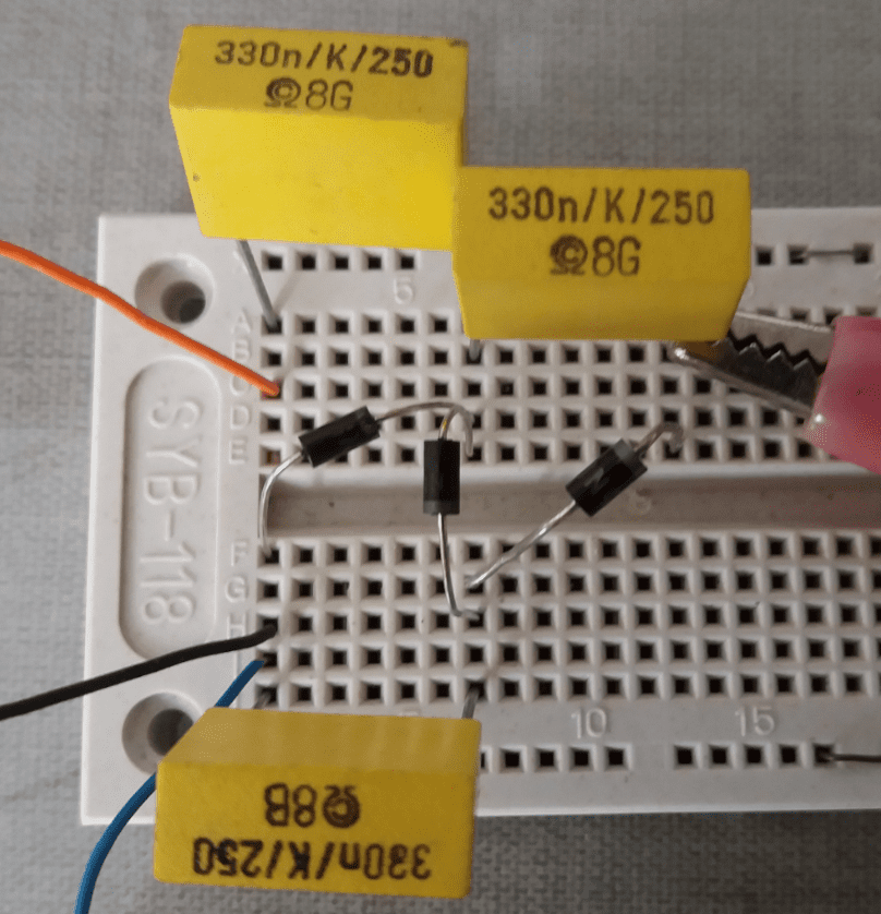
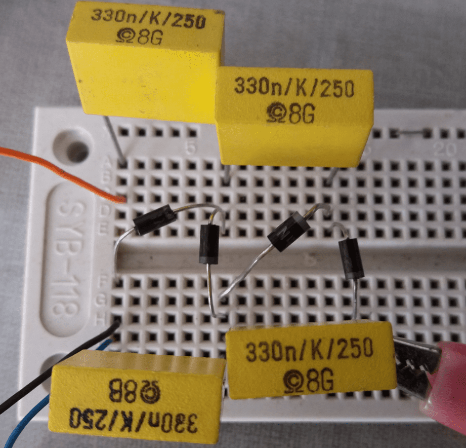
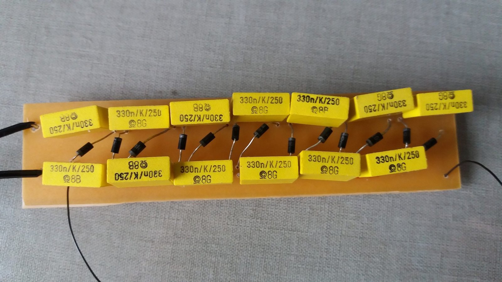
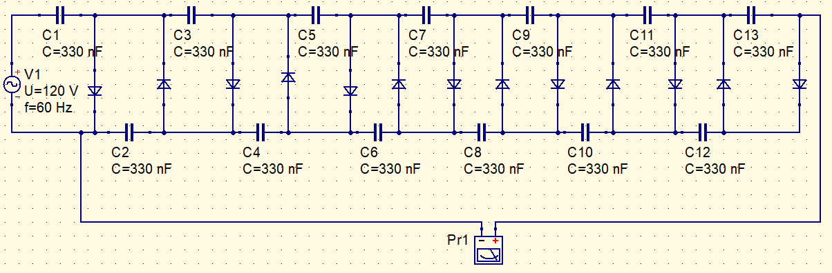
This is the schematics. The capacitors must be in minimum the double of peak voltage of input signal. In my house, the voltage is network of 110 V, therefore, the capacitors voltage is 250 V. Has 13 capacitors and 1N4007 diodes.
The video shows this source working.


