
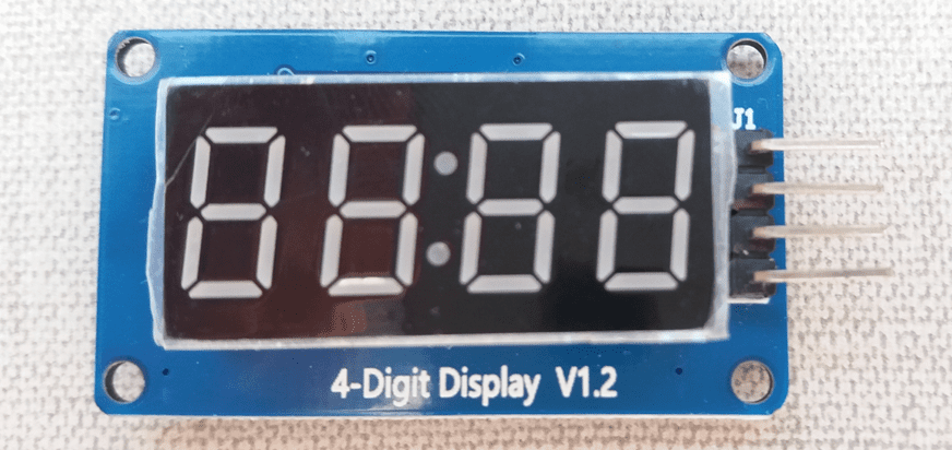
In this post, are shown how to use Arduino with the TM1637 module, a 7-segment display with 4 digits and 3 project examples.
The chip TM1637
It’s an integrated circuit that makes the drive control of a common anode LEDs display. It has a keyboard scan with an improved identification circuit with anti-interference keys. Also has a MCU (Microcontroller unit), that integrates a keyboard scan interface, data latch, and LED drive.
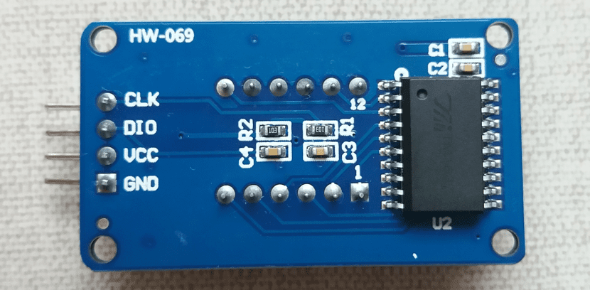
The TM1637 module
Only 4 wires are necessary to make the connection, 2 are for supply. Without this module, would be needed 12 wires to connect the four 7-segment digits to Arduino.
- CLK: Terminal for module’s clock signal.
- DIO: Input and output of data.
Other parameters of the TM1637 module.
- Voltage operation range: 3.3 V to 5 V.
- Consumption current: 80 mA.
- Temperature operation range: -10°C to 80ºC.
To use this display, you must download the library which is on this link.
Projects with TM1637
Real time clock
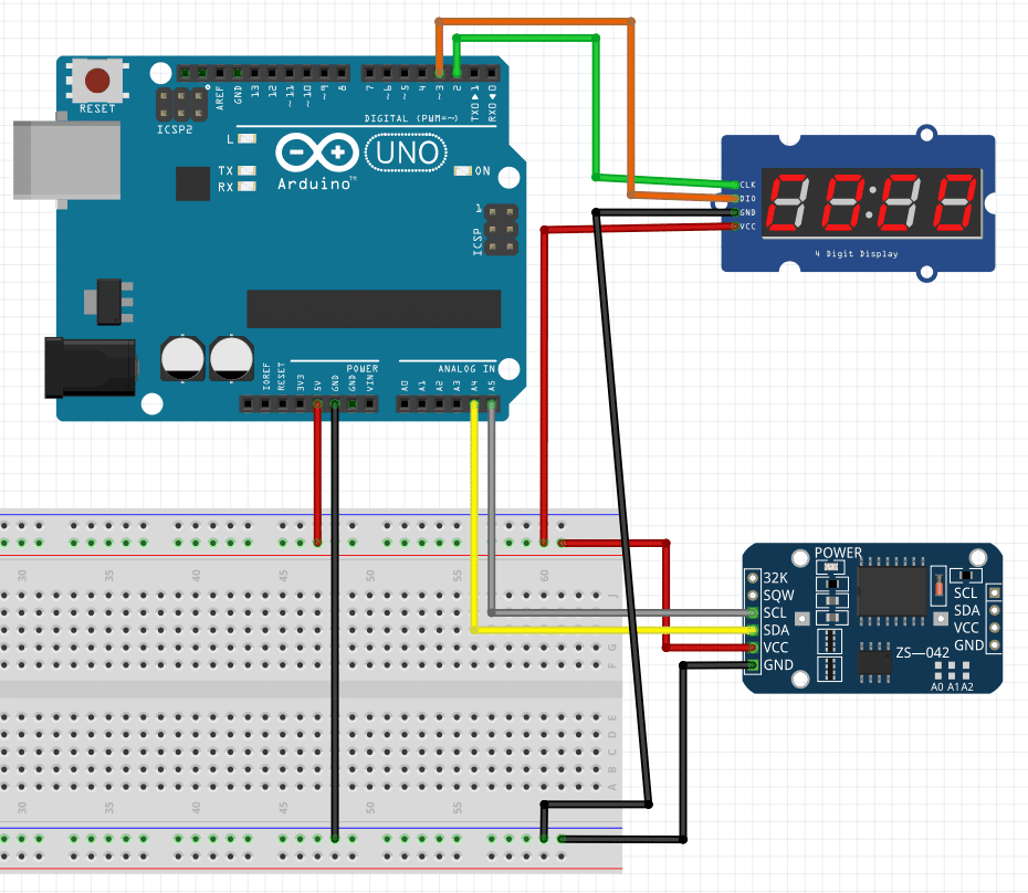
In addition to TM1637, this project uses the RTC module DS3231SN. I already wrote a post about this component, whose link is below.
Arduino tutorial (Part 10)Click here
For this project, it’s recommended to download the library RTClib.h. This is easier to understand than the library shown in the post about DS3231SN module. The link is here. Algorithm below was based on the example provided when downloading RTClib.h.
#include "RTClib.h"
#include <TM1637Display.h>

// Define the connections pins for TM1637 4 digit 7 segment display
#define CLK 2
#define DIO 3

//Initialization of
RTC_DS3231 rtc;
TM1637Display display = TM1637Display(CLK, DIO);

char daysOfTheWeek[7][12] = {"Sunday", "Monday", "Tuesday", "Wednesday", "Thursday", "Friday", "Saturday"};

int displayshow;

void setup () {
  Serial.begin(9600);
//Define display's brightness.
  display.setBrightness(0x0f);
 // Gives a warning if RTC doen not start.
  if (! rtc.begin()) {
    Serial.println("Couldn't find RTC");
    Serial.flush();
    abort();
  }
//If RTC's battery is over. Print the warning on Serial window.
  if (rtc.lostPower()) {
    Serial.println("RTC lost power, let's set the time!");
    // When time needs to be set on a new device, or after a power loss, the
    // following line sets the RTC to the date & time this sketch was
    //compiled
    rtc.adjust(DateTime(F(__DATE__), F(__TIME__)));
    // This line sets the RTC with an explicit date & time, for example to
    //set
    // January 21, 2014 at 3am you would call:
    // rtc.adjust(DateTime(2014, 1, 21, 3, 0, 0));
  }
}

void loop () {
    DateTime now = rtc.now();
    Serial.print(now.year(), DEC);
    Serial.print('/');
    Serial.print(now.month(), DEC);
    Serial.print('/');
    Serial.print(now.day(), DEC);
    Serial.print(" (");
    Serial.print(daysOfTheWeek[now.dayOfTheWeek()]);
    Serial.print(") ");
    Serial.print(now.hour(), DEC);
    Serial.print(':');
    Serial.print(now.minute(), DEC);
    Serial.print(':');
    Serial.print(now.second(), DEC);
    Serial.println();

    //Show minutes and seconds on TM1637. Get the minutes, multiply by 100
    //and add seconds to appear on display.
    displayshow=(now.minute()*100)+now.second();
    //This function serves to show displayshow variable with colon on the
    //middle. The second argument between parentheses is the colon and the
    //false serves to not put zeros on non-used digits.
    display.showNumberDecEx(displayshow,0b11100000,false);
    //If minute is lower than 10, must put a zero in front of it.
    if(now.minute()<10){
      //In this function, the first argument is the number that must show,
      //the second is the quantity of digits that must change and the third
      //is the position on display from 1 to 4.
      display.showNumberDec(0,0,1);
      //This command must be called again to not disappear when shows the
      //aditional zero.
      display.showNumberDec(displayshow,0b11100000,false);
    }

    //Show hours and minutes on TM1637.
    /*displayshow=(now.hour()*100)+now.minute();
    display.showNumberDecEx(displayshow,0b11100000,false);
    //If hour is lower than 10, must be put a zero in front of it.
    if(now.hour()<10){
      display.showNumberDec(0,0,1);
      display.showNumberDec(displayshow,0b11100000,false);
    }*/
    Serial.println();
    delay(1000);
}
Regressive counter

The N transistor is a BJT BC548. Why I didn’t link the buzzer directly to Arduino? If you link it directly, the buzzer will make a small noise when digital input is on low level. When Arduino digital output is connected to a transistor base with a 200 Ω resistor, the transistor acts as a key and the buzzer won’t emit a sound when it’s on low level.
#include <TM1637Display.h>

#define DIO 2 //Digital Pin 2 connected on DIO
#define CLK 3 //Digital Pin 3 connected on CLK

TM1637Display display(CLK, DIO);

int buzzer=8;
int plus_button=5;
int minus_button=6;
int number;
int start_button;

void setup() {
  pinMode(4,INPUT);
  pinMode(buzzer,OUTPUT);
  display.setBrightness(0x0f);
  Serial.begin(9600);
}

void loop() {
//In this case, only two arguments are enough.
  display.showNumberDec(number,false);
  start_button=digitalRead(4);
  if(digitalRead(plus_button)==LOW){
    number++;
  }
  if(digitalRead(minus_button)==LOW){
    number--;
  }
  if(start_button != 1){
    while(number>0){
      number--;
      display.showNumberDec(number,false);
      delay(1000);
      if(number==0){
          digitalWrite(buzzer,HIGH);
      }else{
          digitalWrite(buzzer,LOW);
      }
    }
  }
}
Keypad with password
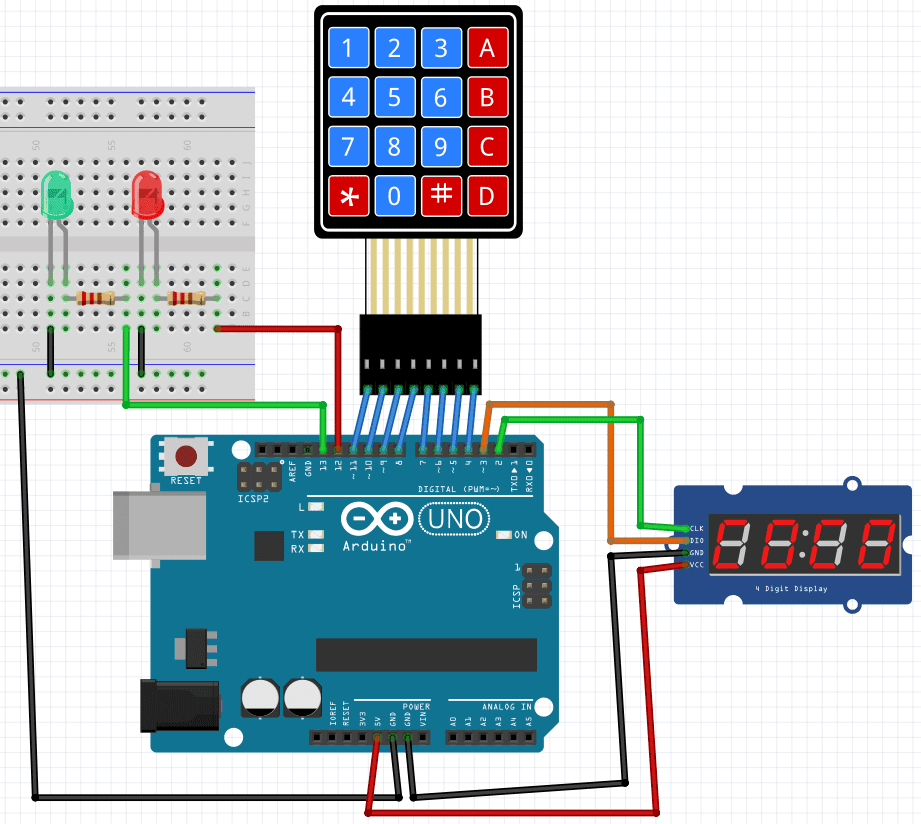
You type on a 4×4 keypad a 4-digit password, that appears on display. If the password is correct, the green LED turns on. Otherwise, the red LED turns on. The code is below.
#include <Keypad.h>
#include <TM1637Display.h>
// Module connection pins (Digital Pins)
#define CLK 2
#define DIO 3

// CONSTANTS
// Define the characters on the keypad layout
const char keys[4][4]={
  {'1','2','3','A'},
  {'4','5','6','B'},
  {'7','8','9','C'},
  {'*','0','#','D'}
};
// Row pins
const byte pinslines[4]={11,10,9,8};
// Column pins
const byte pinsrows[4]={7,6,5,4};

// Create a keypad input class from definitions above
Keypad matrix = Keypad(makeKeymap(keys),pinslines,pinsrows,4,4);

// Create a display object, specifying pin parameters (Clock pin, Data pin)
TM1637Display display(CLK, DIO);

int RedLed=12;
int GreenLed=13;

// Record the code which the user has entered
char data[] = "    ";
// That variable indicates the current position on the code.
int sequenceNum = 0;

// Updates the display to show the current code entered by the user
void updateDisplay() {
  // Initialise a new blank display array
  uint8_t displayData[] = { 0, 0, 0, 0 };
  // Loop over each character in the code
  for (int i = 0; i < (sizeof(data) / sizeof(data[0])); i++) {
  // Display the numbers if press from 0 to 9 on keypad.
  if (data[i] >= '0' && data[i] <= '9') {
      displayData[i] = display.encodeDigit((int)data[i] - 48);
    }
    // If press *, clear the display.
    else if (data[i] == '*') {
      memset(data, 0, sizeof(data));
      sequenceNum = 0;
    }
    // For the # character, display parallel lines
    //at the top and bottom of the digit
    else if (data[i] == '#') {
      displayData[i] = 0b00001001;
    }
    else if(data[i] == 'A'){
      displayData[i] = 0b11110111;
    }
    else if(data[i] == 'B'){
      displayData[i] = 0b01111100;
    }
    else if(data[i] == 'C'){
      displayData[i] = 0b00111001;
    }
    else if(data[i] == 'D'){
      displayData[i] = 0b01011110;
    }
  }
  // Pass the data array to the display
  display.setSegments(displayData);
}

// Flash the current value of the display on and off
void flashDisplay() {
  // Define an "empty" array (i.e. all segments off)
  uint8_t OFF[] = { 0, 0, 0, 0 };
  // Toggle between the current value and the empty value
  for (int i = 0; i < 4; i++) {
    delay(250);
    display.setSegments(OFF);
    delay(250);
    updateDisplay();
  }
}
void setup() {
  Serial.begin(9600);
//Determine display brightness.
  display.setBrightness(4);
  pinMode(RedLed,OUTPUT);
  pinMode(GreenLed,OUTPUT);
}

void loop() {
  // Get the keypad input this frame
  char key = matrix.getKey();
  // Has a key been pressed?
  if (key) {
    // Log it to the serial output
    Serial.println(key);
    // Set the current position of the code sequence to the key pressed
    data[sequenceNum] = key;
    // Increment the counter
    sequenceNum++;
    // Update the display to reflect the current sequence
    updateDisplay();
    // If the player has entered all 4 digits of a code
    if (sequenceNum == 4) {
      Serial.print(F("Code entered: "));
      // Log the whole code to the serial output
      Serial.println(data);
      // Take action based on the code entered
      if (strcmp(data, "123A") == 0) {  //Write the password here. The //password shown is 123A.
        digitalWrite(RedLed,LOW);
        digitalWrite(GreenLed,HIGH);
        delay(2000);
        digitalWrite(RedLed,LOW);
        digitalWrite(GreenLed,LOW);
      }else{
        digitalWrite(RedLed,HIGH);
        digitalWrite(GreenLed,LOW);
        delay(2000);
        flashDisplay();
        digitalWrite(RedLed,LOW);
        digitalWrite(GreenLed,LOW);
      }
      // Clear the data array
      memset(data, 0, sizeof(data));
      sequenceNum = 0;
      // Update the display
      updateDisplay();
 }
  }
}
hi
when i run code for \”Keypad with password \” in ide Arduino, The program gives an error on \”&\” in this line :
if (data[i] >= \’0\’ && data[i] <= \'9\') {
(https://www.electricalelibrary.com/en/2022/06/16/4-digits-display-tm1637-with-arduino/)
Replace (&); with ‘&’.
hi,thanks a lot
You’re welcome.