
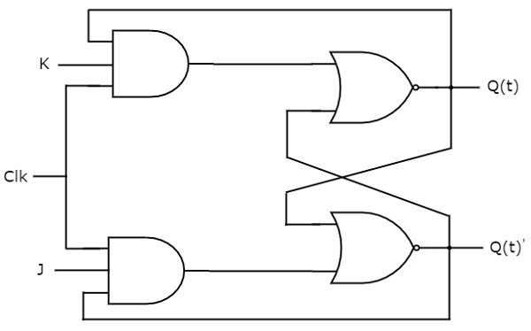
This post is the continuation of the post about flip-flops. The counters are a flip-flop sequencial arrangement and it is one of the most important applications of this type of digital circuit.
To understand flip-flops click in this button.
 Flip-flopClick here
Asynchronous counter
This is the simplest counter, a flip-flop output is linked to the other flip-flop`s clock input. Below is a counter with 4 flip-flops therefore 4 bits. In (a) we have the flip-flop connections and in (b) there are four outputs and the clock signal. It is called counter because it counts from 0000 to 1111. When it reaches 1111, it restart the counting.
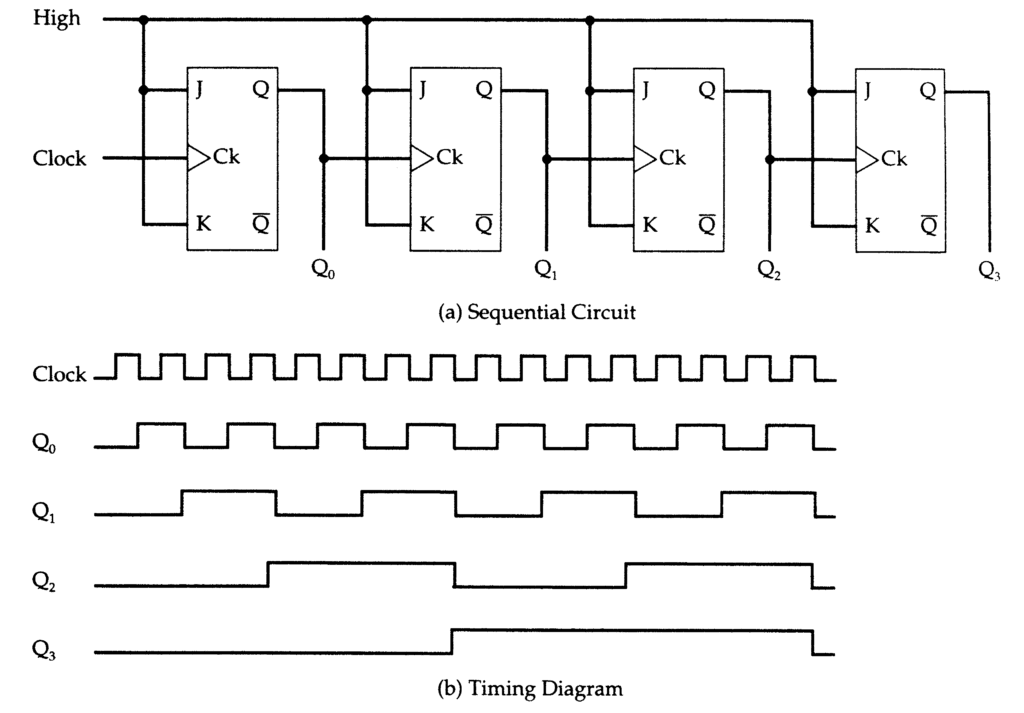
The integrated circuit 74LS293 is an exemple of 4 bits counter.
N module counter
Don`t you want a counter to count until the maximum value and yes to a lower number? It is necessary a module N counter (whose N is an arbitrary number). For exemple, you want a module 6 with 3 flip-flop, just connect a NAND door’s inputs to Q1 and Q2 and the NAND door’s output in all flip-flop’s clear.

When the counter’s output reach 110, the NAND door will be 0 and the counter is restarted. To have a descending counter, which counts from maximum value to minimal, you must connect the negative output of one flip-flop to the another`s clock.

Synchronous counters
One of the disadvantages of asynchronous counter is the delay propagation which accumulate until the most significant bit. These delays are caused due the flip-flop trigger during the output transition of previous flip-flop. With the accumulation of delays, some binary numbers aren`t counted.

To solve this problem, appeared the synchronous counter or parallel whose clock signal is connected to all flip-flops. To count like the asynchronous it is needed to add some AND doors and use the J and K inputs. Only the flip-flop of least significant bit have J and K in constant high level.

The 74LS193 is a 4 bits synchronous counter which can be used like ascending or descending. Here is a circuit I build which uses this chip and a 74LS14 as clock. In this circuit, it is possible to change to ascending or descending mode just changing the connections in wires.
The needed materials to build this circuit are:
- 4 leds;
- 4 470 Ω resistors and 1 kΩ resistor;
- 1 470μF electrolytic capacitor;
- 1 74LS193 and 1 74LS14;
- 1 4 AA batteries support;
- 4 AA batteries;
- Some wires;
- Printed circuit board.
