
In this post, will be taught how to supply LEDs properly and use in your projects. In addition to some ideas of circuit projects with LEDs.
To see how LED works, click in the button below.
 LEDsClick here
Calculating with LEDs
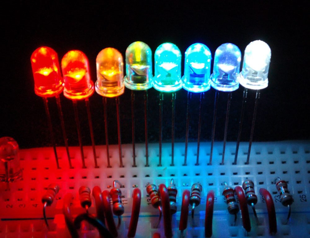
LEDs are nothing more than diodes which emit light, however the direct voltage (Vd) is bigger than in diode and depends on the color. In many cases, LEDs with same color can show different voltages. This table shows the average voltage band of each LED with different color, based on measures made by myself.

The infrared color is invisible to our eyes, but can be seen by cellphone camera. This purple light is the infrared radiation.

LEDs need to be in series with a resistor to not burn, unless the supply voltage is small enough. The resistor to the LED depends of the voltage you wish to apply. This table shows the value which the resistor must have to each voltage band.
 To other voltage values, can use the formula below.

R=\frac{VDC-Vd}{I}
Where VDC is the voltage supply, Vd is the voltage in the LED and I is the current.
Using other types of LEDs
This is the correct form to use the RGB LED with 4 terminals. The RGB LED can be common cathode or anode, I only have common anode, in this setting, the longest terminal must be linked to positive pole. If it was common cathode, this same terminal would be linked in the ground.


Exists a RGB LED with only 2 terminals, is linked like a common LED, but change color with time. It has an internal integrated circuit with voltage regulator, making it change color.

This is the bicolor LED, has two antiparallel LED between themselves with different colors.


Some circuit projects with LEDs
Now I will show some circuits with LEDs. This is the control of a RGB LED with potentiometers (variable resistors).

The circuit in a printed circuit board, in case you don’t know how to make a printed circuit board, click here.

Materials:
- 3 47 Ω resistors;
- 3 10kΩ potentiometers;
- 1 RGB LED;
- Wires and board.
This circuit blinks LEDs in sequence. Uses an astable 555 and the decade counter CD4017BE, click in this link to see the datasheet (chip’s data).

In this circuit, LEDs blinks in sequence in counterclockwise direction, with the switch, can put in slow or fast mode.

Materials:
- Wires and printed circuit board;
- 1 NE555;
- 1 CD4017BE;
- 1 switch with 1 pole;
- 2 resistors (22kΩ and 470kΩ);
- 1 100nF ceramic capacitor;
- 2 electrolytic capacitors (1 μF x 50 V and 22 μF x 25V);
- 6 LEDs (2 reds, 2 blues and 2 greens).
This is a LED tape.

To use, you must take out part of silicone which shows the supply with a blade.

After the cuts, must stay in this form.

Then, sold the terminals and turn on the voltage supply, in case 12 Volts.


