
Synchronous generators are used in many types of power plants to convert mechanical energy of turbines in electrical energy.
Alternator’s operational principle
Synchronous generators also are called alternators. In an electrically excited synchronous generator (EESG), rotor’s winding is supplied by a DC power source, generating a magnetic field. When rotor rotates, a senoidal alternate voltage is induced in each stator’s winding. This is the principle of electromagnetic induction, have already been explained in the post “How a hydro power plant works?“.

The value of induced voltage E_{A} in winding A of stator is:
E_{A}=V\cdot sin(\omega t)
Being that V is amplitude voltage, \omega is angular speed and t is time. While voltages in B and C phases respectively are.
E_{B}=V\cdot sin(\omega t-120^{\circ})
E_{C}=V\cdot sin(\omega t+120^{\circ})
Formula of synchronous speed of rotating magnetic speed Ns in rpm (rotations per minute). f is frequency in Hz and P is number of poles.
Ns=\frac{120f}{P}
The formula above shows a relation between number of poles and synchronous speed. When lower the speed, higher must be the number of poles.
Components
Between rotor and stator, there is a space called air gap. The slots are where wires are placed.
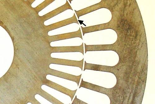
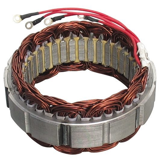
All alternator’s windings must have a core made made of silicon steel sheets separated by insulating films. The material is to increase intensity of magnetic flux and it is laminate to reduce loss for parasite currents. Around the cores, wires made of copper are wired. Stator wires are linked in star or delta. These links will be explained in a future post.
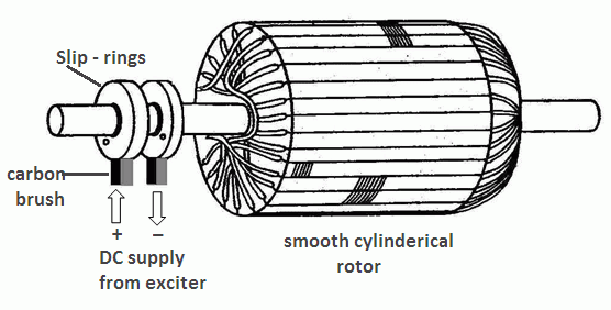
The EESG has slip rings, where rotor receives DC voltage through graphite brushes.
Some synchronous generators have permanent magnets made of neodymium alloy instead of windings. Are used to generate energy in wind turbines.

To avoid overheating, generator’s armor have openings to air circulation and a fan linked to axis for cooling.

Automatic voltage regulator
With load variation, voltage output changes, it must stay inside a band. A electronic circuit called automatic voltage regulator controls field current in rotor, to control rotating magnetic field.

Rotor
Rotor for synchronous generators can be one of two types. Orange circles are slots where copper wires are positioned.
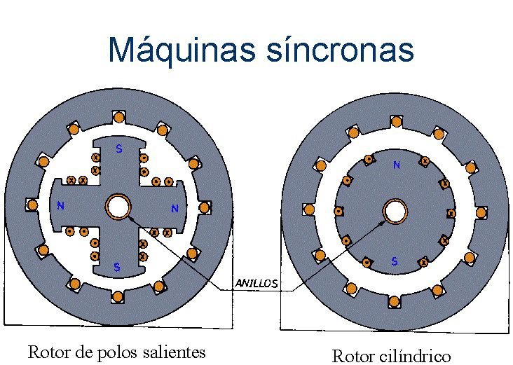
Synchronous generators with protruding poles, are used to low speed applications. Possess big circumference and lower length. Machines with cylindrical rotor present few poles, therefore are for high speed. Has bigger length and smaller diameter in comparison with protruding poles type.
In the next post of energy area, I will show ways to supply rotor’s wires.
