
The balun is used in telecommunication circuits, usually, it’s connected to an antenna. The operation and some types are today’s subjects.
What the balun do?
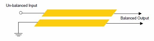
Balun is the abbreviation of balanced-unbalanced, this passive component’s functions are:
- Make the connection between balanced and unbalanced. For example, between a balanced antenna and an unbalanced transmission line.
- Impedance transformation.
Balanced and unbalanced lines
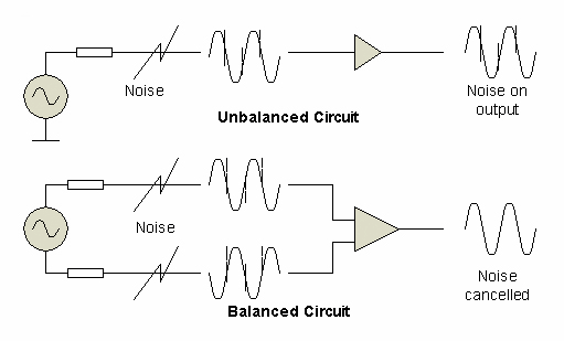
When a line or circuit is balanced, it means that input and output currents are equal and in opposite directions. It’s told that the currents are symmetric in relation to ground.
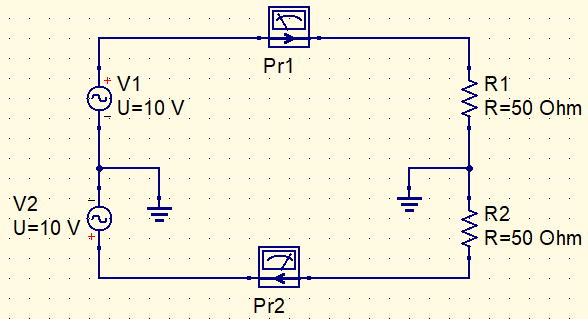

Transmission lines in radiofrequency (RF) circuits must be balanced to protect themselves against external electromagnetic waves and to not distort signals.
Without balun, the antenna’s radiation pattern is distorted, harming directivity.
The importance of impedance matching (or transformation) in RF circuits
Physically, impedance is the measure of opposition to electric current in a determined voltage. The impedance matching is important to have maximum power transfer from the circuit to antenna and vice-versa. Therefore, higher efficiency as possible.
Voltage and current baluns
In a voltage balun, potential differences are equal and symmetrical in relation to the ground. While in a current balun, currents are equal and in the opposite direction.
Some types
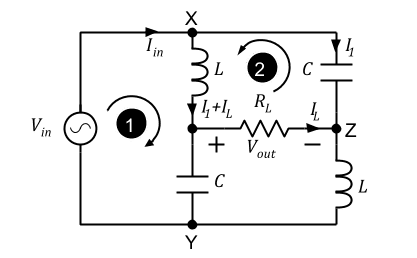
LC

It’s a low cost solution, made of 2 capacitors and 2 coils. Used in narrowband applications, because this circuit has a resonance frequency f_{0}, whose formula is:
f_{0}=\frac{1}{2\pi \sqrt{LC}}
L and C are respectively inductance and capacitance.
Transformer
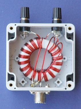
It’s the most known type, used in impedance matching between the TV antenna and unbalanced cable. The impedance rate depends on the number of turns in the primary and secondary windings. If secondary has the double of turns than the primary, input impedance becomes:
Z_{I}=Z_{L}(\frac{N}{2N})^2=\frac{Z_{L}}{4}
N is the number of turns and Z_{L} is the load impedance in output. This type only works for frequencies below 1 GHz, above this value, parasite capacitances between the wires and Foucault currents become higher.Microstrip
Made in a printed circuit board, the strip’s length must have a quarter of wavelength of RF signal. Exist many balun microstrip structures.
Exist many types of balun that will be shown in other posts.

I wanted to record what i read, hugs this subject is very interesting i love your blog website wonder.
Your website is amazing congratulations, visit mine too:
https://strelato.com
.