
In this post, it’s shown how to control an Arduino with a smartphone using an easy method, through a Bluetooth module HC-05 or HC-06.
To know how Bluetooth technology works, click on link below.
HC-05 and HC-06 modules
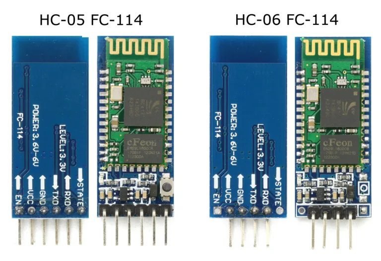
In addition to number of pins, as shown in the image above, the HC-06 can only be used as slave, by that, only receive data and transmit to Arduino. While HC-05 also can operate on master mode, by that, can transmit data to other Bluetooth modules. On presented projects on this post, HC-05 is used only to receive commands via cellphone. Functions of module’s pins are:
- VCC: positive supply voltage, can go from 3.6V to 6V. Can be directly connected to Arduino’s 5V terminal.
- GND: the ground, must be linked to Arduino’s GND.
- TXD: data transmission terminal, must be linked to Arduino’s digital pin 0.
- RXD: data receiver terminal, must be connected to Arduino’s digital pin 1.
- STATE: this pin is connected to the LED. Indicates if the module is connected with some device via Bluetooth. If it’s connected, return level “HIGH” (5V), otherwise, return “LOW” level (0V).
- EN: it’s used to configurate the device as master. With this pin, can set the module as data mode or AT command mode, the latter is to be used as master. By manufacturing standart, HC-05’s default state, without receive an external symbol, is data mode.
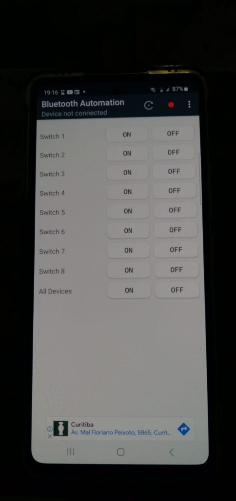
The app
Exist many apps to control Arduino via Bluetooth. For projects on this post, I picked the app “Bluetooth Automation HC-05”, whose link is here.
Projects with HC-05 module
Controlling devices by cellphone
Necessary materials:
- Arduino Uno.
- Protoboard.
- Wires.
- Resistors: 1 of 470Ω and 1 of 1kΩ.
- LED of any color.
- Buzzer.
- Zener diode.
- IRF640N MOSFET.
- DC motor.
- HC-05.

The following code.
char data;

int LED=12;
int buzzer=11;
int motor=10;

void setup() {
  Serial.begin(9600);
  pinMode(LED,OUTPUT);
  pinMode(buzzer,OUTPUT);
  pinMode(motor,OUTPUT);
}

void loop() {
  data=Serial.read();
  Serial.println(data);
  switch(data){
    case 'A':
    digitalWrite(LED,HIGH);
    break;

    case 'a':
    digitalWrite(LED,LOW);
    break;

    case 'B':
    digitalWrite(buzzer,HIGH);
    break;

    case 'b':
    digitalWrite(buzzer,LOW);
    break;

    case 'C':
    digitalWrite(motor,HIGH);
    break;

    case 'c':
    digitalWrite(motor,LOW);
    break;
  }
}

This project must work as shown on the video.
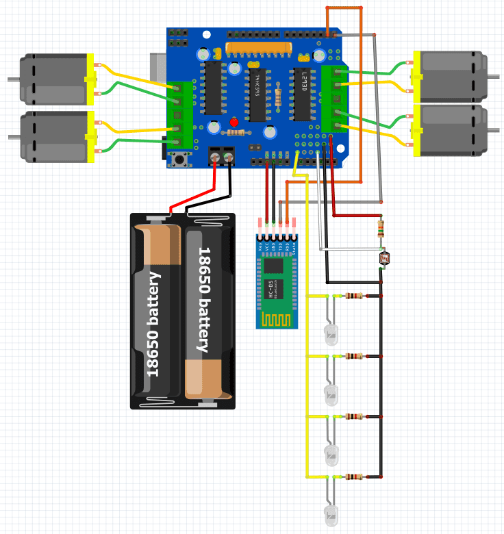
Vehicle controlled by cellphone
Material list for this project:
- Arduino Uno.
- Robot Kit chassis 4WD with Mecanum wheels.
- H bridge shield for 4 motors.
- Wires.
- 1 pole and 3 terminals key.
- 2 Li-ion rechargeable batteries with 4,2V and 12000mAh.
- Support for batteries.
- A LDR sensor.
- Resistors: 1 of 15kΩ and 4 de 1kΩ.
- High brightness white LEDs.
- Bluetooth module HC-05.
The algorithm below, when LDR don’t detect light, the LEDs turn on.
#include <AFMotor.h>
//Analog pins        A0 A1 A2 A3 A4 A5
//Digital pins 12 13 14 15 16 17 18 19
char dados;

int LEDS=14;
const int LDR=A3;
int stateLDR=0;
AF_DCMotor motor1(1,MOTOR12_64KHZ);
AF_DCMotor motor2(2,MOTOR12_64KHZ);
AF_DCMotor motor3(3,MOTOR34_64KHZ);
AF_DCMotor motor4(4,MOTOR34_64KHZ);

void setup() {
  Serial.begin(9600);
  pinMode(LEDS,OUTPUT);
  pinMode(LDR,INPUT);
  motor1.setSpeed(150);
  motor2.setSpeed(150);
  motor3.setSpeed(150);
  motor4.setSpeed(150);
}

void loop() {
  stateLDR=analogRead(LDR);
     if(stateLDR<950){
        digitalWrite(LEDS,LOW);
        mechanum();
      }else{
        digitalWrite(LEDS,HIGH);
        mechanum();
      }
}
void mechanum(){
    while(Serial.available()>0){
    dados=Serial.read();
    Serial.println(dados);
    switch(dados){
      case 'A':  //All wheels spin on the same direction.
      motor1.run(FORWARD);
      motor2.run(BACKWARD);
      motor3.run(FORWARD);
      motor4.run(BACKWARD);
      break;

      case 'a':  //All wheels spin on the same direction.
      motor1.run(BACKWARD);
      motor2.run(FORWARD);
      motor3.run(BACKWARD);
      motor4.run(FORWARD);
      break;

      case 'B':
      motor1.run(BACKWARD);
      motor2.run(BACKWARD);
      motor3.run(BACKWARD);
      motor4.run(BACKWARD);
      break;

      case 'b':
      motor1.run(FORWARD);
      motor2.run(FORWARD);
      motor3.run(FORWARD);
      motor4.run(FORWARD);
      break;

      case 'C':
      motor1.run(RELEASE);
      motor2.run(BACKWARD);
      motor3.run(RELEASE);
      motor4.run(BACKWARD);
      break;

      case 'c':
      motor1.run(RELEASE);
      motor2.run(FORWARD);
      motor3.run(RELEASE);
      motor4.run(FORWARD);
      break;

      case 'D':
      motor1.run(BACKWARD);
      motor2.run(RELEASE);
      motor3.run(BACKWARD);
      motor4.run(RELEASE);
      break;

      case 'd':
      motor1.run(FORWARD);
      motor2.run(RELEASE);
      motor3.run(FORWARD);
      motor4.run(RELEASE);
      break;

      case 'E':
      motor1.run(FORWARD);
      motor2.run(RELEASE);
      motor3.run(RELEASE);
      motor4.run(BACKWARD);
      break;

      case 'e':
      motor1.run(BACKWARD);
      motor2.run(RELEASE);
      motor3.run(RELEASE);
      motor4.run(FORWARD);
      break;

      case 'F':
      motor1.run(RELEASE);
      motor2.run(FORWARD);
      motor3.run(BACKWARD);
      motor4.run(RELEASE);
      break;

      case 'f':
      motor1.run(RELEASE);
      motor2.run(BACKWARD);
      motor3.run(FORWARD);
      motor4.run(RELEASE);
      break;

      case 'G':
      motor1.run(BACKWARD);
      motor2.run(BACKWARD);
      motor3.run(FORWARD);
      motor4.run(FORWARD);
      break;

      case 'g':
      motor1.run(FORWARD);
      motor2.run(FORWARD);
      motor3.run(BACKWARD);
      motor4.run(BACKWARD);
      break;

      case 'H':
      motor1.run(RELEASE);
      motor2.run(RELEASE);
      motor3.run(FORWARD);
      motor4.run(FORWARD);
      break;

      case 'h':
      motor1.run(RELEASE);
      motor2.run(RELEASE);
      motor3.run(BACKWARD);
      motor4.run(BACKWARD);
      break;

      case '@':
      motor1.run(RELEASE);
      motor2.run(RELEASE);
      motor3.run(RELEASE);
      motor4.run(RELEASE);
      break;
    }
  }
}
Important tip: it’s possible to use Arduino’s analog pins as digital pins. In case you want to add sensors with this shield or need more digital inputs or outputs, just declare a digital pin with numbers from 14 to 19, as shown in the code’s beginning.

Demonstration video.

Tam da aradığım elinize sağlık
You’re welcome.