
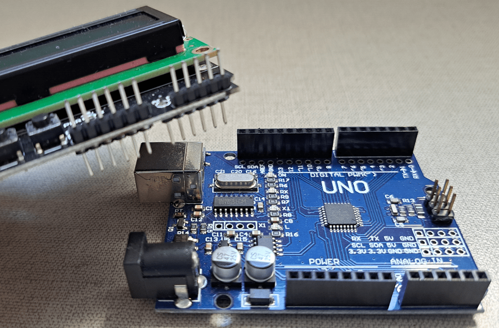
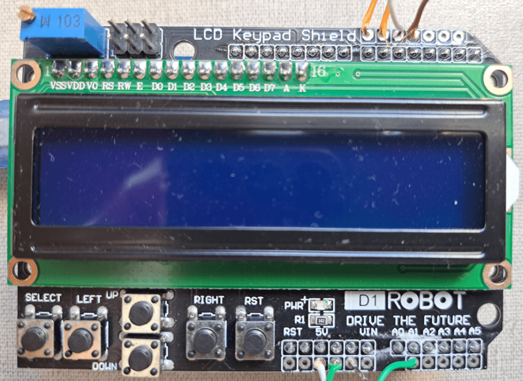
This post’s subject is the LCD Keypad module, which allows to control a LCD display with buttons without wires and a protoboard.
Post about LCD operationClick here
Post about LCD constructionClick here
Operation and use
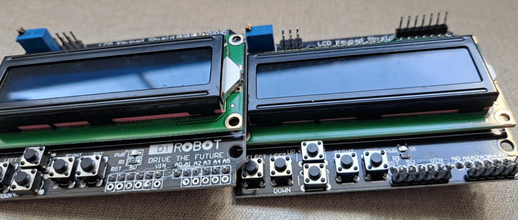

In some modules, background LED doesn’t work. I have one with this problem and I didn’t find out how to solve it yet.
Project examples
Testing LCD Keypad
Simply test LCD display and buttons. It’s necessary to use ‘LiquidCrystal.h’ library. Part 7 of Arduino tutorial shows how to use this library. The algorithm below tests the module.
#include <LiquidCrystal.h>

//**Project settings**
//They are according to shield.
#define allButtons A0

#define Nobtpressed 0
#define btSELECT 1
#define btLEFT   2
#define btUP     3
#define btDOWN   4
#define btRIGHT  5

//Define connections and create object for access.
const int rs = 8, en = 9, d4 = 4, d5 = 5, d6 = 6, d7 = 7;
const int backLight = 10;
LiquidCrystal lcd(rs, en, d4, d5, d6, d7);

void setup(){
  pinMode(backLight,OUTPUT);
  lcd.begin(16,2);
  digitalWrite(backLight,HIGH); //To background LED keep turned on.
}

void loop(){
  int valButton=analogRead(allButtons); //Analog reading of A0.
  if ((valButton < 800) && (valButton >= 600)) {
     lcd.clear();
     lcd.print("Select");
  } else if ((valButton < 600) && (valButton >= 400)) {
     lcd.clear();
     lcd.print("Left");
  } else if ((valButton < 400) && (valButton >= 200)) {
     lcd.clear();
     lcd.print("Down");
  } else if ((valButton < 200) && (valButton >= 60)) {
     lcd.clear();
     lcd.print("Up");
  } else if  (valButton < 60) {
     lcd.clear();
     lcd.print("Right");
  }
}
When pressing a button, must appear the name on LCD. Reset (RST) button restarts the program.
Flywheel simulator
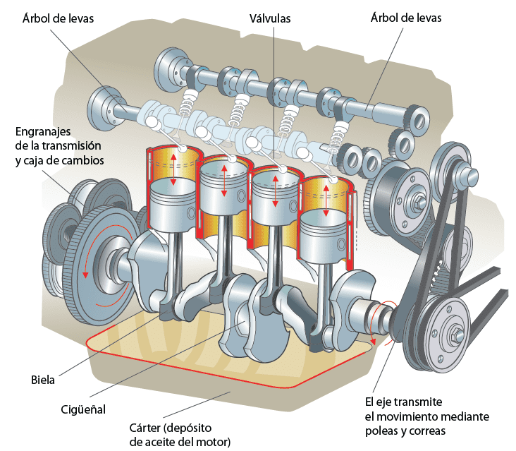
What’s a flywheel (on vehicles)? It’s a gear, linked to the crankshaft, and has an inductive or hall effect sensor to measure crankshaft’s rotation angle. The sensor sends electric signals to an electronic center or ECU, informing about combustion engine’s stages and points where valves open and close.
Attending requests, this is a project that generates a flywheel signal with a Hall effect sensor at 5 volts.
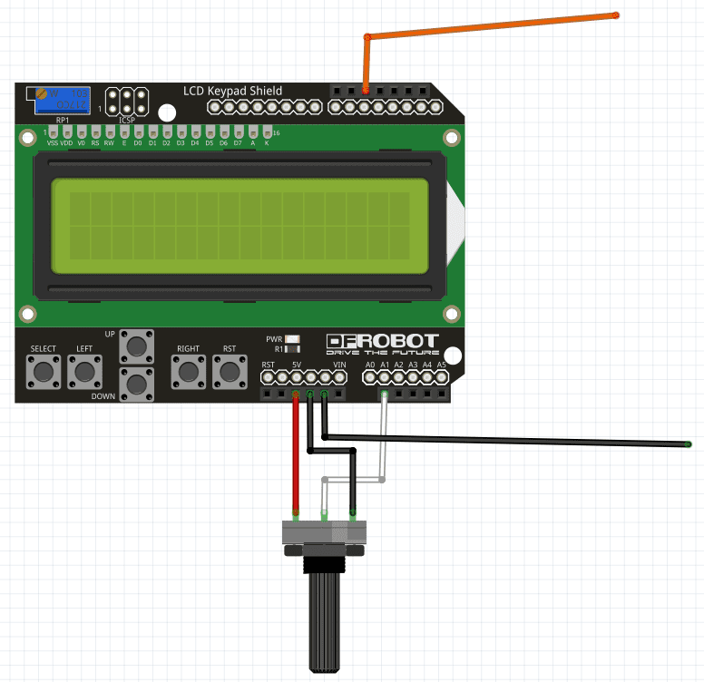
In this project, you choose the number of teeth and fails on flywheel. The maximum number of teeth is 58 and the fail number can’t be higher than teeth number. The potentiometer varies signal frequency from 1Hz to 170Hz. 170Hz is the engine’s frequency when it’s at 10200 rpm (rotations per minute).
#include <LiquidCrystal.h>

//**Project settings**
//They are according to shield.
#define allButtons A0

#define Nobtpressed 0
#define btSELECT 1
#define btLEFT   2
#define btUP     3
#define btDOWN   4
#define btRIGHT  5

//Define connections and creates the objectives for access.
const int rs = 8, en = 9, d4 = 4, d5 = 5, d6 = 6, d7 = 7;
const int backLight = 10;
int signal=11;
unsigned int Tnumber=0; //Número de dentes.
unsigned int Fnumber=1; //Número de falhas.

const int pot=A1;
int potstate=0;
int frequency=0;
int halfPeriod=0;

int running=0;
LiquidCrystal lcd(rs, en, d4, d5, d6, d7);

void setup(){
  pinMode(backLight,OUTPUT);
  pinMode(signal,OUTPUT);
  pinMode(pot,INPUT);
  lcd.begin(16,2);
  lcd.print("Phonic wheel:");
  digitalWrite(backLight,HIGH);
  Serial.begin(9600);//Just to test the potentiometer.
}

void loop(){
  lcd.setCursor(0,1);
  lcd.print("Teeth:");
  lcd.print(Tnumber);//Number of teeths.
  lcd.setCursor(8,1);
  lcd.print("Fails:");
  lcd.print(Fnumber);//Number of fails.
  potstate=analogRead(pot);
  frequency=map(potstate,0,1023,1,170);//map function makes potentiometer vary from //1Hz to 170Hz.
  halfPeriod=1000000/(2*frequency); //Calculating half period.
  int valButton=analogRead(allButtons);
  if ((valButton < 800) && (valButton >= 600)) { //SELECT button
    running=1;  //Transmite o sinal ao apertar SELECT.
  } else if ((valButton < 600) && (valButton >= 400)) { //LEFT button
     Tnumber=Tnumber-1;
     delay(500);
  } else if ((valButton < 400) && (valButton >= 200)) {//DOWN button
     Tnumber=Tnumber-1;
     delay(500);
  } else if ((valButton < 200) && (valButton >= 60)) {//UP button
     Fnumber=Fnumber+1;
     delay(500);
  } else if  (valButton < 60) { //RIGHT button
     Tnumber=Tnumber+1;
     delay(500);
  }
  if(Fnumber>=Tnumber){
     Tnumber=1;
     Fnumber=0;
  }
  if(Tnumber>58){
    Tnumber=0;
    lcd.setCursor(7,1);
    lcd.print(" ");
  }
  if(running==1){
     phonicwheel();
  }
}
void phonicwheel(){
  lcd.setCursor(0,1);
  lcd.print("Running...     ");
    for(int i=0;i<(Tnumber-Fnumber);i++){
     digitalWrite(signal,HIGH);
     delayMicroseconds(halfPeriod);
     digitalWrite(signal,LOW);
     delayMicroseconds(halfPeriod);
    }
}
I didn’t test this simulator in an ECU in a vehicle. I made this project only for didactic purposes. Therefore, I don’t know if it will work in a real ECU. If you wish, you can test it at your own risk.
