
Today are shown how Hall effect works, a magnetic sensor using this phenomena and how o use it in projects with Arduino.
How Hall effect works?
If a conductor, conducting an electrical current I, is within a magnetic field B, the electrons in conductor will receive a magnetic force. Consequently, will have a separation of positive charges (space without electrons) and negative charges (electrons).

Magnetic force F_{m} over the electron is calculated with the equation below. Where \vec{v} is speed vector and q is particle’s electrical charge.
\vec{F_{m}}=q\vec{v}\times \vec{B}
Separation of positive and negative charges creates an electric field which exerts a force with opposite direction to magnetic force. When electric force has equal intensity to magnetic one, electrons are no longer deviated. Charge separation creates a difference of potential which can be measured. This is the equation which calculates Hall voltage V_{H}.
V_{H}=\frac{IB}{ned}
- n is charge density.
- e is electron’s charge, which is latex]1,6*10^{-19}C[/latex].
- d is thickness of conductive plate.
R_{H}=\frac{1}{ne}
Hall effect sensor
Soon was realized that Hall effect phenomena can be used to detect and measure magnetic fields. This is the Hall effect sensor KY-003. Has a LED to indicates if received magnetic field, a 680 Ω is to prevent LED’s burnout and 3144EUA-S, a Hall effect switch to high temperatures.

- Voltage operation range: 4.5 to 24 V.
- Operation temperature: -40ºC to 85ºC.
- Dimensions: 18.5 mm x 15 mm (0.728 in x 0.591 in).
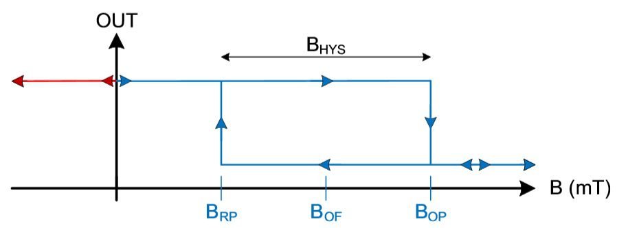
When the intensity of a magnetic field reaches a value B_{OP}, output signal will stay at low level. If magnetic field goes below a determined value B_{RP}, output will be high level. It happens because the sensor has a Schmitt-Trigger circuit, making the sensor to have a digital output.

Has 3 pins: The one with “-” signal is GND, “S” is the digital signal pin, can be connected in any digital pin of Arduino, and middle terminal is Vcc, linked in 5V. This is the algorithm to test Hall effect sensor. In presence of a magnetic field, LEDs of sensor and Arduino pin 13 lights up. On contrary, it is off.

This sensor can detect magnetic polarity. With experiments, I realized that in sensor’s front side, LED lights up with North pole. While in opposite side, LED turns on with South pole.
Projects applying Hall effect sensor will be shown in another post.
