The SPI, an abbreviation of Serial Peripherical Interface, is another communication protocol used in microcontrollers and peripherical.
How SPI works?
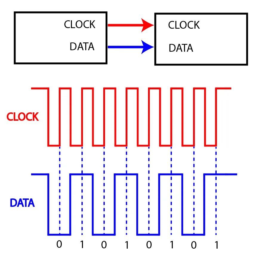
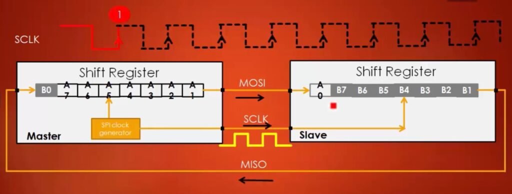
Motorola implemented this standard for the first time in 1970. Just like I2C, it’s a synchronous serial communication protocol. In this communication method, transmitting and receiving devices must have their clock signals synchronized, i.e., must change bits at the same time. A solution is to send the transmitter’s clock signal to receivers.
SPI operates in full-duplex mode, i.e., both sides of communication can exchange information between themselves at the same time.

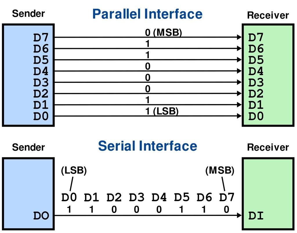
Serial and parallel interface
The SPI bus
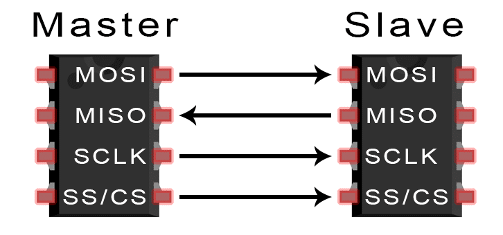
The communication interface SPI requires 4 wires between master (sends commands) and slave (receives commands).
- SCLK: serial clock signal. Both must have the same signal because this interface is synchronous.
- MOSI (Master Output Slave Input): communication channel for the master or controller to send data to the slave or peripheral.
- MISO (Master Input Slave Output): channel to peripheral send data to controller.
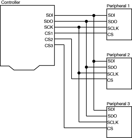
- SS or CS (Slave/Chip Select): master must send a signal on the “LOW” level to communicate with a receiver. Won’t have exchange information if its on “HIGH” level or 1.
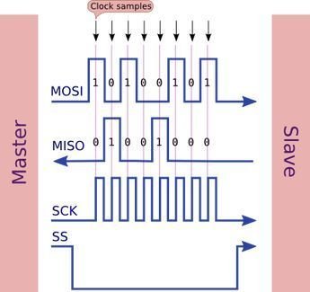
Clock parameters
It’s possible to adjust two parameters on the clock channel to configure SPI bus: polarity and phase. Clock polarity (CPOL) determines if clock’s idle state will be “1” or “0”. While clock phase (CPHA), determines if data sampling is done on clock rise or clock descend, this parameter also depends on polarity.

Advantages and disadvantages in relation to I2C
The advantages of SPI are:
- It doesn’t need addressing bits, making transmission simpler.
- Higher transmission rate than I2C.
- Two-way communication (full-duplex). While I2C is half-duplex, it’s two-way also, but the information flux in a direction has to wait until the transmission in the opposite direction ends.
- Has lower power consumption.
The disadvantages:
- This interface requires 4 wires for each peripheral, while I2C only needs two.
- Only one master is viable.
- There’s no error connection.
- There’s no verification of data reception.