
The communication protocol I2C is very used in microcontrollers such as Arduino. But what is I2C? It’s this post’s subject.
What is I2C?
Was developed by Philips in the 1980s. It’s currently the most popular synchronous communication protocol for short distances. The name I2C is abbreviation for Inter-Integrated Circuit. Allows communication between many peripherals, integrated circuits, microcontrollers, sensors, etc.

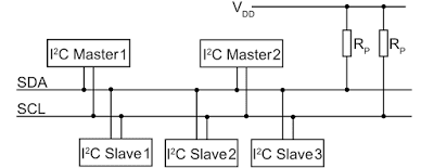
The I2C allows communication between many masters and slaves in a single 2 wire bus. The SCL carries clock signal and SDA is where data travels. Clock is a square wave signal, that coordinates actions of sequencial digital circuits.
How it works?
Pull-up resistors
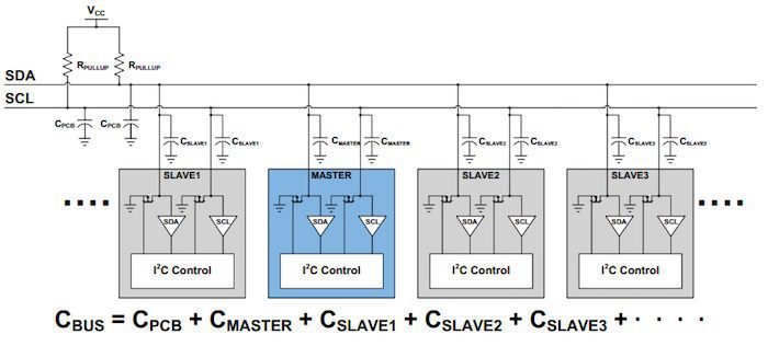
The SDA and SCL buses need pull-up resistors, so that the lines stay in “HIGH” level, when there is no data communication. Devices on bus are “open-drain”, consome electric current, but can’t provide current to bus. The pull-up resistors allow the communication between many devices in digital values “0” and “1”.
The formula to calculate pull-up resistor minimum value R_{p(min)}.
R_{p(min)}=\frac{(V_{bus}-V_{OL})}{I_{OL}}
Where:
- V_{bus} is voltage on bus.
- V_{OL} is the maximum voltage on “LOW” level.
- I_{OL} is current on “LOW” level.
To calculate maximum pull-up resistor level.
R_{p(max)}=\frac{t_{r}}{0,8473\cdot C_{b}}
Where:
- t_{r} is the signal’s rise time, in other words, the time it takes to go from “LOW” level to “HIGH”.
- C_{b} is total capacitance on bus, which must include parasitic capacitances between SDA and SCL wires and, between wires and ground.
I2C message
Each device on network has an address from 7 to 10 bits. Starts from most significative bit (MSB) until the least significative (LSB).

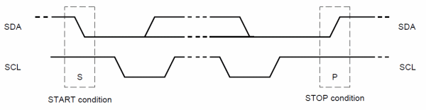
The master sends a start condition to a device, which is a transition from “HIGH” level to “LOW” on SDA, before SCL do the same transition. For a condition end of transmission, SDA makes a transition from “LOW” to “HIGH” after SCL.
After device’s address, comes the read/write bit. It indicates if the master is sending data to slave (0 bit) or requesting data (1 bit). The ACK/NACK is the acknowledgment bit, always comes after a data frame. Serves to receiver device or slave to inform to emitter if receives the data frame. The ACK/NACK bit is on “0” level, when the slave receives data frame, the bit is on “1” level, if it does not receive the bit sequence.

Transmission speed
| Modes | Maximum speed |
| Standard (Sm) | 100 kbps |
| Fast (Fm) | 400 kbps |
| High speed (Fm+) | 3,4 Mbps |
| Ultra fast (Hs-mode) | 5 Mbps |
