A multivibrator is a circuit that has two states in output, high or “1” and low or “0”. Multivibrators can be of three types: Astable, monostable, and bistable. This post shows the operation and design of these circuits.
Astable multivibrators
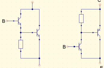
This is a classic astable multivibrator with 2 NPN transistors.
How it works? When C1 is loading, T2 is in saturation allowing passage of electrical current through T2, and C2 is discharged. After C2’s discharge, it starts to charge by a current that passes through R4 until T1’s base terminal, allowing T1’s saturation. So T1 conducts, C1 is discharged and the cycle continues. In the videos shown, the green part is positive voltage, the yellow points are electric current, grey part is ground, which is zero voltage. While red is a negative voltage.
To design this circuit, first has to define the astable’s oscillation frequency, in this example will be 20 Hz. So, period T will be:
T=\frac{1}{f}=\frac{1}{20}=0,05s
The period must be divided in two because it’s necessary to calculate the time conduction of two transistors. T1 and T2 are periods of T1 and T2 transistors respectively.
T=T1+T2
T1=0,69\cdot R2\cdot C2
T2=0,69\cdot R1\cdot C1
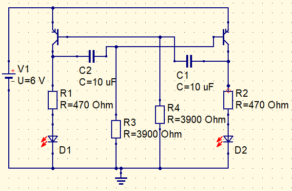
Values of capacitors C1 and C2 are 10 μF and were chosen arbitrarily. T1 and T2 value 0.025 s, therefore:
T1=0,69\cdot R2\cdot C2
0,025=0,69\cdot R1\cdot 10\mu
R1=3623,1\Omega
Was used the closest value I have available, which is 3.9 kΩ. The transistor used can be a BC, I chose BC548. LEDs are red, therefore let’s consider voltage drop V_{LED} as 2 V. Voltage supply V1 is 6 V.
Rc=\frac{(V1-V_{LED})}{Ic}
The maximum of collector current Ic BC548 can support is 100 mA, let’s use 10 mA. Therefore, resistances of R3 and R4 are:
Rc=400\Omega
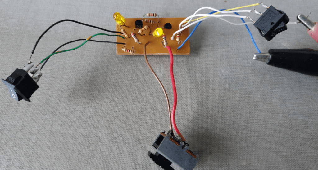
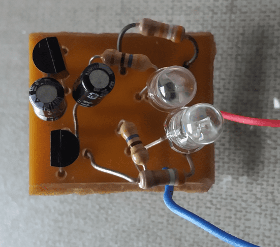
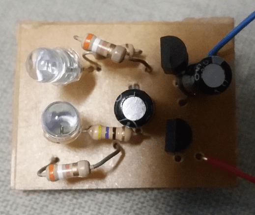
Let’s use the commercial value of 470 Ω. This is the circuit in a printed circuit board, to LEDs blink slower, and increase the value of resistors or capacitors.
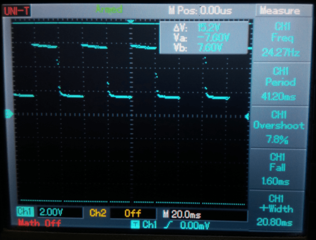
Output signal in one of transistor’s collector.

Astable with PNP
It is possible to make an astable with 2 PNP transistors. Using the same values of the previous circuit, replacing BC548 with BC558 will have the same result.
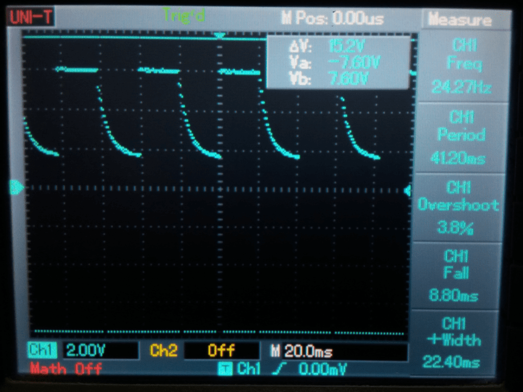
Output signals in collector of transistors.
Monostable multivibrators
There is only one stable state. In this circuit, transistor’s base is linked to collector of another one with a resistor. In a stable state, T2 is cut while T1 is in saturation and C1 capacitor is charged.
When switch S1 is closed, T2 conducts and T1 is cut. C1 is discharged, sending current to T2’s collector, and D1 LED is blinked because T1 in cut produces a voltage between collector and emitter.
The duration of an unstable state depends on R1 and C1, below is the period’s formula.
T=0,693\cdot C1\cdot R1
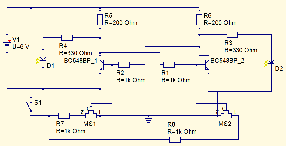
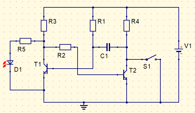
These are the schematics and printed circuit of monostable respectively.
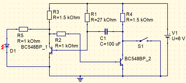
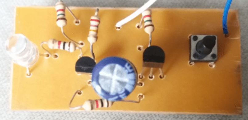
R3 and R4 limit collector current and R2 protects BC548BP_2 from heating and limits base current. Pressing the button, the LED will stay on for a period of time before turning off.
Bistable multivibrators
In this bistable multivibrator, a transistor stays cut and another saturated or vice versa. When SET input goes to low level, T1 stays in cut and D1 LED turns on because the voltage is at a high level in T1’s collector. While T2 conducts and D2 LED stays off. If RESET stays at a low level, T2 enters in cut, D2 turns on and T1 saturates.

In the video below, outputs change with high level (H) pulse.
In practice, in the circuit at the beginning of topic, transistors operate independently of each other, and outputs can stay both at high or low levels. A flip-flop doesn’t work that way. This bistable was made to behave more realistically like a flip-flop. If S1 is closed, two outputs can stay in equal states of low or high. With S1 open, will behave like the circuit in the video above.