In this tutorial, it is shown how to control stepper motors with Arduino. In addition to a example of project.
I already wrote a post describing operation of stepper motors, click in the button to access the post.
Integrated circuits to control stepper motors
A stepper motor must be controlled by digital signals and the latter must be amplified by transistors in Darlington mode. This mode is a pair of transistors positioned in a way that behave like a single transistor. A Darlington pair’s gain is product of gain of two transistors. For example, if two transistors have gain 100 , the pair’s gain will be 10,000. This is a Darlington pair of integrated circuit ULN2004APG. These pairs have the function to amplify current to charge stepper motor’ coils.

Each triangle with a circle in diagram is a Darlington pair.

Exist other chips with prefixe ULN which have the same function. In this post is used ULN2004APG as example.
Controlling a stepper motor

Here is shown how to control an unipolar stepper motor AK57HY of Akiyama using Arduino and ULN2004APG chip. This is the motor’s wire configuration, datasheet is in this link.

Vermelho=red, branco=white, verde=green, amarelo=yellow, preto=black e azul=blue.
This is the schematics to connect motor to Arduino. I used ULN2003A in software, but connection is the same.

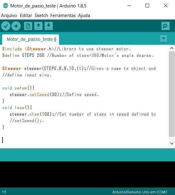
This is the algorithm that makes motor turn. The Stepper.h library makes easier code implementation.
Shield to stepper motors
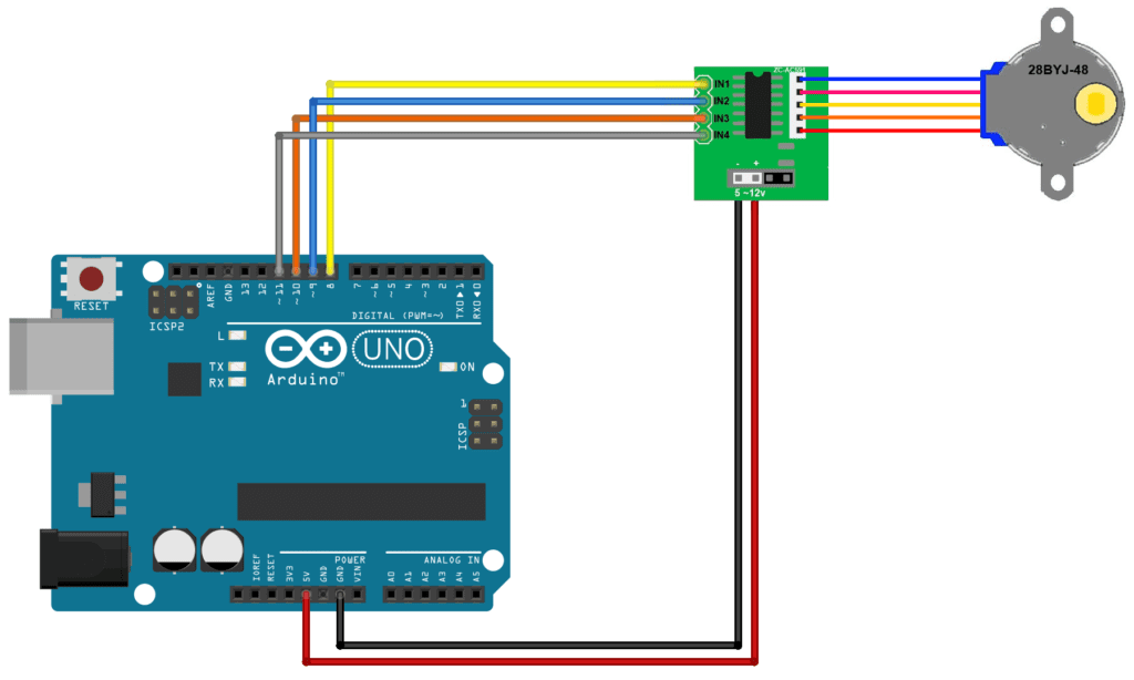
Here is shown the control of a bipolar stepper motor 28BYJ-48 with a shield showed below.

This time, it is demonstrated how to change motor’s rotation direction. These are schematic and algorithm respectively. Motor must turn 180 degrees in one direction and then 180 degrees in opposite direction.

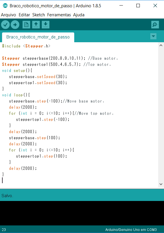
Robotic arm with stepper motors
This is a project of robotic arm only with stepper motors. The base motor is AK56H of Akiyama and it is controlled by chip ULN2004APG.

The top stepper motor is 28BYJ-48 and it is controlled by it`s circuit driver. Schematics and code respectively.

Robotic arm complete.

Video of robotic arm in operation.