
This is the second part of synchronous generator. The subject is an introduction about ways to provide direct current to synchronous machine’s rotor.
Link to see the first part of synchronous generators Click here
Exciter
Exciter is the name given to direct current source for rotor of synchronous generator. It is an electric machine smaller than alternator.
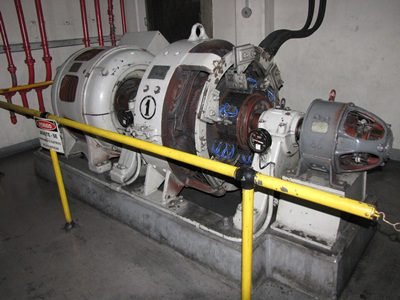
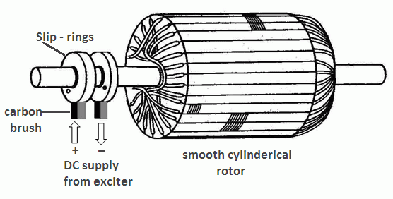
It’s on the same axis of turbine and supplies direct current to rotor through slip rings and carbon brush.
 To keep constant voltage, magnetic field in rotor must be constant. Therefore, an automatic voltage regulator (AVR) must detect output voltage variation in synchronous generator and controls field current provided by exciter.
Pilot exciter
In some rotor supply systems, there is a pilot exciter, which controls main exciter’s stator field. Has a permanent magnet rotor, can be on the same axis of turbine and alternator, be connected to axis through a gear set or separately turned on by a motor.
DC excitation or shunt
In this system, the main exciter is a DC generator which provides current to rotor. In a DC generator, commutator is divided in segments electrically insulated from each other. Preventing current to change direction. DC generator is also called dynamo.
In winding’s outputs of synchronous generator, exist step-down current and power transformers, these send voltage signal from generator to AVR. The AVR controls stator windings of exciter. This feedback system is present in all excitation modes.

Field current (which goes to stator) in pilot exciter is regulated by rheostats, these are variable resistances. In case of failures, a field brake opens and a resistor in parallel with exciter field receives inductive discharge, this security system is used in other systems.

DC method isn’t used for big generators anymore. The reasons are:
- Rings and brushes require a lot of maintenance.
- Sizable power loss in brushes.
- Increase of load reduces output voltage and AVR needs more excitation current.
- Sparks during abrupt variation of load.
Static AC excitation
In this system, current to alternator’s rotor come from an AC exciter. AVR receives three phase signal from alternator output with step-down transformers and controls a three phase rectifier bridge of thyristors. These are power electronic components and subject to another post.
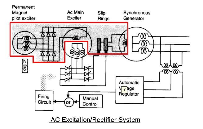
The voltage in main exciter’s stator comes from a pilot exciter or it’s own output. Another rectifier bridge is used to main exciter’s stator receives direct current.

In some configurations, both rectifier bridges are controlled by AVR. Regulation response is faster due to thyristor control. However, slip rings require maintenance.
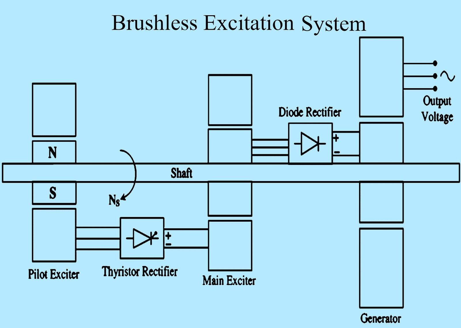
Brushless excitation
In this system, slip rings aren’t used neither graphite brushes. Possess a rotating rectifier bridge of diodes, mounted on the shaft between main exciter and synchronous generator and, a thyristor network controlled by AVR to main exciter`s stator.
This is an example of rotating diode bridge to synchronous generator. High power diodes are components with wires.

This exciting system is currently the most used for big generators. Due to quickly response time and requires less maintenance.
