This is the third and last part of the series about BJT transistor polarization. Other circuit configurations are shown.
The other parts can be accessed by clicking on the following buttons.
How to polarize BJT transistor? (Part 1) Click here
How to polarize BJT transistor? (Part 2) Click here
Polarization of BJT transistor by voltage division

This configuration is more stable than the emitter’s stable polarization. By that, variations of collector current variations (I_{C}) and collector-emitter voltage (V_{CE}) are very small when β changes. Exist two known methods for analyzing this circuit.
Accurate analysis
Using this circuit to apply accurate analysis, calculating values of I_{C}, V_{CE}, I_{B}, V_{E} and V_{B}.

It’s necessary a Thévenin equivalent circuit of area inside the red quadrilateral, whose output, where there are the terminals, is pointed by the arrow.

Calculating resistance and Thévenin voltage respectively.
R_{th}=R1||R2=\frac{R1\cdot R2}{R1+R2}=\frac{39k\cdot 8,2k}{39k+8,2k}=6,775k\Omega
E_{th}=\frac{R2\cdot V1}{R1+R2}=3,12V
Applying the equation below to calculate base current I_{B}.
I_{B}=\frac{E_{th}-V_{BE}}{R_{th}+(\beta +1)\cdot R_{E}}
I_{B}=\frac{3,12-0,7}{6,78k+(120 +1)\cdot 1k}=18,93\mu A\simeq 19\mu A
I_{C}=\beta \cdot I_{B}=120\cdot 19\mu =2,28mA
Calculating collector-emitter voltage V_{CE}.
V_{CE}=V_{CC}-I_{C}\cdot (R_{C}+R_{E})=18-2,28m\cdot (3,3k+1k)=
Finding the remaining values.
I_{E}=I_{B}+I_{C}=2,299mA\simeq 2,3mA
V_{E}=I_{E}\cdot R_{E}=2,3m\cdot 1k=2,3V
V_{BE}=V_{B}-V_{E}\rightarrow 0,7=V_{B}-2,3\rightarrow V_{B}=3V
Approximate analysis
To know if you can apply approximate analysis in a circuit, you must make the following test. If the condition below is true, you can apply this analysis.
\beta \cdot R_{E}\geq 10\cdot R_{2}
120 \cdot 1k\geq 10\cdot 8,2k
120k\geq 82k
As the condition above is true.
V_{B}=\frac{R_{2}\cdot V_{CC}}{R_{1}+R_{2}}
V_{B}=\frac{8,2k\cdot 18}{39k+8,2k}=\frac{147,6}{47,2}=3,12V
V_{BE}=V_{B}-V_{E}\rightarrow V_{E}=3,12-0,7=2,42V
I_{E}=\frac{V_{E}}{R_{E}}=\frac{2,42}{1k}=2,42mA
In this analysis, can consider I_{E}\cong I_{C}. Calculating V_{CE}.
V_{CE}=V_{CC}-I_{C}\cdot (R_{C}+R_{E})
V_{CE}=18-2,42m\cdot (3,3k+1k)=7,594V
DC polarization with voltage feedback

Another stable configuration, using Kirchhoff’s law for voltages in the mesh of emitter and collector’s terminals, can calculate current base as:
I_{B}=\frac{V_{CC}-V_{BE}}{R_{B}+\beta (R_{C}+R_{E})}
Applying the same Kirchhoff’s law in collector-emitter mesh can obtain collector-emitter voltage V_{CE}.
V_{CE}=V_{CC}-I_{C}(R_{C}+R_{E})
An important detail, current that passes by R_{C} isn’t collector current I_{C}. But the one that enters the collector of BJT transistor.
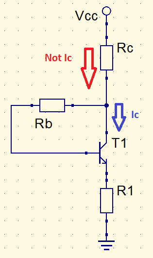
The “Not Ic” current is the sum of base and collector currents. However, collector current and the one which passes through resistor R_{C} are much higher than I_{B}. The equation shown before was demonstrated considering these current as approximately equal. With this proximity, saturation current I_{Csat} can be calculated as:
I_{Csat}=I_{Cmax}=\frac{V_{CC}}{R_{C}+R_{E}}
Other polarization configuration with BJT transistor
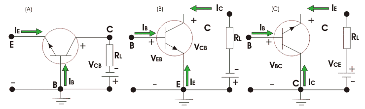
The BJT polarizations are common base, emitter, and collector. The circuits shown until now are common emitter because the circuit’s input is linked to base and output to collector.
Problems involving other configurations can be solved by applying Kirchhoff’s law for voltages.
Common base example
Considering this common base circuit.

Applying Kirchhoff’s law for voltages on the left mesh.
-V_{EE}+R1\cdot I_{E}+V_{BE}=0
I_{E}=\frac{V_{EE}-V_{BE}}{R_{1}}
I_{E}=\frac{8-0,7}{2,2k}=3,32mA
Calculating V_{C} and considering emitter current proximately equal to collector’s (I_{C}\cong I_{E}).
V_{CC}=R2\cdot I_{C}+V_{CB}
10=1,8k\cdot 3,32m+V_{CB}
Since voltage in the base is zero.
V_{CB}=V_{C}=4,024V
And finally, finding the value of V_{CE}.
V_{E}-V_{EE}=R_{1}\cdot I_{E}
V_{E}-(-8)=2,2k\cdot 3,32m
V_{E}=-8+7,304=-0,696V
V_{CE}=4,024-(-0,696)=4,72V
Common collector example

Applying agains Kirchhoff’s law for voltages.
V_{CC}=I_{B}R1+V_{BE}+I_{E}R2-V_{EE}
V_{CC}+V_{EE}-V_{BE}=I_{B}R1+I_{E}R2
V_{CC}+V_{EE}-V_{BE}=I_{B}R1+I_{B}(\beta +1)R2
I_{B}=\frac{V_{CC}+V_{EE}-V_{BE}}{R1+(\beta +1)R2}
I_{B}=\frac{6+6-0,7}{330k+(120 +1)1,2k}=0,02377m=23,77\mu A
I_{E}=(\beta +1)I_{B}=(120+1)\cdot 23,77\mu =2,88mA
V_{E}-V_{EE}=I_{E}R2
V_{E}-(-6)=2,88m\cdot 1,2k
V_{E}=-2,544V
Common base with pnp transistor

V_{EE}-V_{BE}=Re\cdot Ie
8-0,7=3,3k\cdot Ie
Ie=2,21mA
Finding Vc.
Vc-Vcc=Ic\cdot Rc
Vc-(-12)=2,21m\cdot 3,9k
Vc=-3,37V