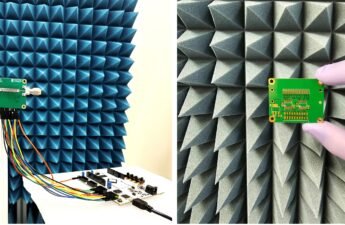
This is a project of a vehicle with tracks controlled by a pair of RF modules and intergated circuits HT-12E (encoder) and HT-12D (decoder).
The transmitter circuit
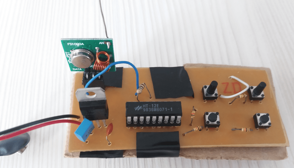
Material list
- RF transmitter module.

- 3 female connectors module for the terminals of transmitter module.
- 9 V battery.
- Battery clip.
- Printed circuit board (PCB).
- Wires.
- Voltage regulator L7805CV.
- Capacitors: 1 300 nF polyester and 1 100 nF ceramic.
- Resistors: 1 1MΩ (brown, black and green) and 4 10 kΩ (brown, black and orange).
- 4 normally open buttons.
- HT-12E.
- Support for integrated circuit with 18 pins, to put the HT-12E.
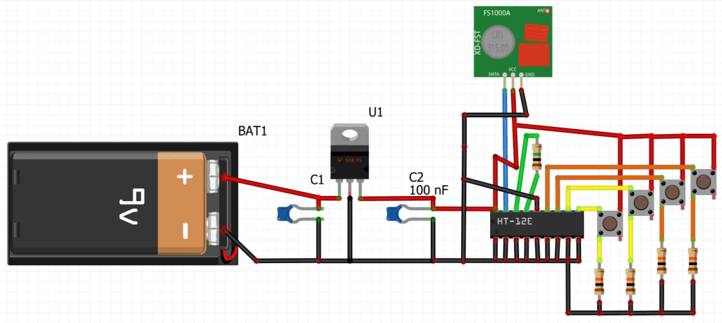
Schematics
Remote control vehicle

Materials list
- Receiver module.

- Protoboard.
- Capacitors: 1 300 nF polyester, 1 100 nF ceramic and 1 220 μF electrolytic.
- Voltage regulator L7805.
- Resistors: 5 150 Ω (brown, green and brown) and 1 56 kΩ (green, blue and orange).
- Decoder integrated circuit HT12D.
- 5 LEDs of various colors.
- Wires.
- L293D H bridge.
- 8.5 to 9 cm for the antenna.
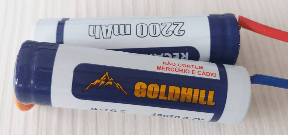
- 2 rechargeable batteries of 3.7 V and 2200 mAh or higher.
- Track chassis with 2 DC motors.

Schematics

Why did I used protoboard and not PCB to build the receiver? With a phenolite board, a button were pressed and when it’s released, the motor kept turning, not receiving more commands. The cause was the brushed motor that produced electromagnetic interference when turning. Phenolite board aren’t adequate for RF circuits that involve motors. The following video shows the vehicle’s operation.