
In this post are shown 2 digital electronics projects, using DIP integrated circuits: luminous effect with 74HC595 and a semaphore.
Project with 74HC595
This project creates light effect using the shift register 74HC595. This chip has already been shown in the post whose link is below.
Material list:
- Printed circuit board (PCB).
- 1 integrated circuit 555.
- 1 electrolytic capacitor of 4.7 μF x 100V (the voltage can be from 16 V).
- Resistors: 8 of 220 Ω, 1 of 470 Ω and 1 of 10 kΩ.
- LEDs: 2 reds, 2 greens, 2 blues and 2 yellows.
- 1 push-button switch with 6 pins.
- 1 74HC595.
- 2 male connectors pins.
- 4 AA batteries.
- 1 support for 4 batteries.

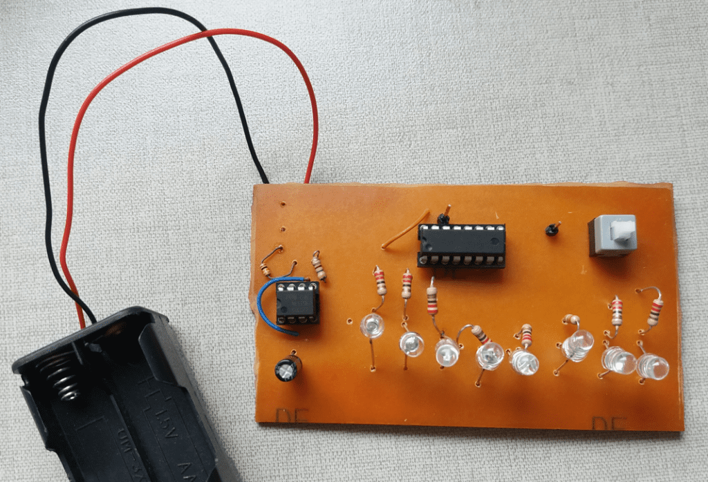
How does it work?
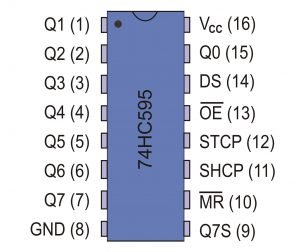
Input enable (pin 13) must be linked to the GND or the chip won’t work. The pin 10 is on “HIGH” level, because the master reset function isn’t used. When the latch (pin 12) is on “LOW” level, data that come from pin 14 enter in the shift register. When latch passes to “HIGH” level, the chip can’t receive data and stored data on shift register are transferred to storage register.


In this project, the latch (pin 12) and the clock pin 11 receive the same square signal from 555 astable. When there is a connection between the connectors, when the button is pressed, LEDs turned on in sequency and pressing it again, LEDs turned off in sequency.
Semaphore
This is a semaphore without microcontroller. Using an astable 555, logic doors and the integrated circuit 4017.
Post about the operation of 4017Click here
Material list:
- Printed circuit board.
- Wires.
- 1 100 kΩ potentiometer.
- 1 10 μF x 25 V electrolytic capacitor.
- Resistors: one of 1 kΩ and other of 15 kΩ.
- 1 CD4017.
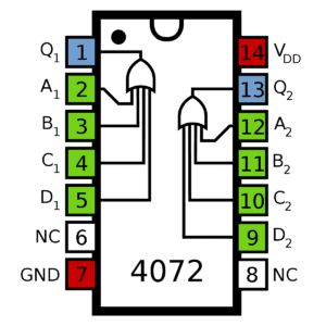
- 1 CD4072.
- One 74LS02.
- 8 male connectors for wires.
- LEDs: 2 reds, 2 yellows and 2 greens. Each one must have a resistor in series with values that can be between 220 and 470 Ω. Or each set of 3 colors can have only 1 resistor.

How does it work?
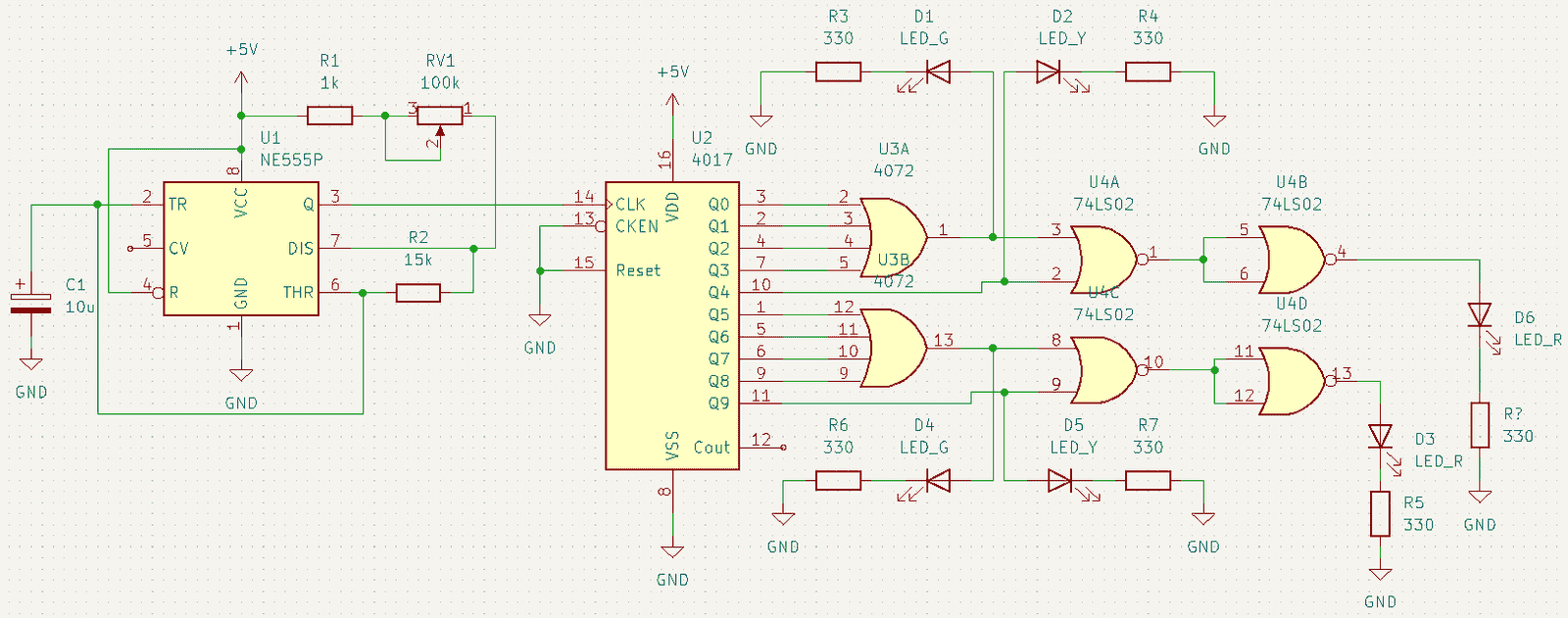
The 555 astable generates a low frequency signal, it can be adjusted by potentiometer. This signal goes to the 4017, whose outputs are linked to a combinational circuit with 8 inputs that makes the LEDs light up like in a semaphore. If one is green, other must be red and vice-versa.


JAHA KARICHA BHARI KHARAP KARICHA SO SAD
What do you mean?