In this post, it is shown how to design a BJT amplifier with voltage divider on common emitter mode. Two examples of projects are presented.
To know BJT transistor operation, click on this link.
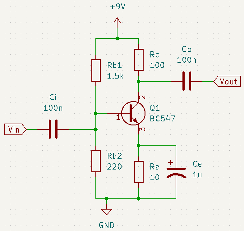
Common emitter amplifier with NPN transistor

The first step is to choose the transistor. In this example, was chosen the BC547B.
Calculating collector resistor
The value of supply voltage is 9 V and the voltage gain
is -100. These values were chosen arbitrarily. You must look at characteristic curve graphic of BC547, to find the Q point. This point must be where the input AC signal can be amplified without distortion.

The following figures show what happens with the output waveform, when quiescent point is too close to cut off and saturation regions.
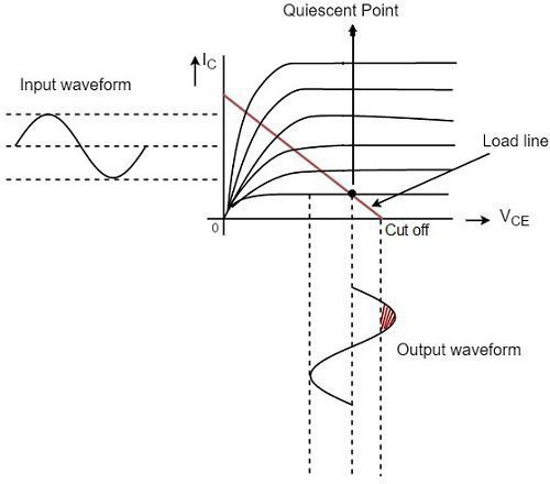

The Q point must be where is half of power supply. In this case,
is equal to 4.5 V. Picking up the base current curve
, collector current (
) is approximately 48 mA. Below, the voltage gain formula for common emitter amplifiers.
Equation to find value.
is emitter current, that’s the sum of base (
) and collector (
) currents.
I_{E}=I_{C}+I_{B}=48m+0.2m=48.2mA
Finding and collector resistor (
).
r_{e}=\frac{26m}{48.2}=0.539\Omega
-100=\frac{-R_{C}}{0.539}
R_{C}=53.9\Omega
The closest commercial value that I have for Rc is 100 Ω. But could use a 56 Ω or 75 Ω.
Calculating emitter resistor
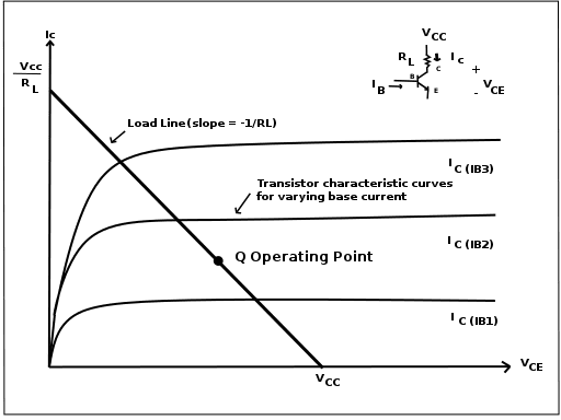
Plotting a load line on BC547 characteristic curve, connecting Q point to axis point where equals 9, the saturation collector current (
) is approximately 85 mA. Calculating emitter resistor
.
R_{E}=5.88\Omega
The closest available commercial value is 10 Ω.
Calculating base resistors
The transistor’s β or can be measured with a multimeter or a LCR meter.

value must attend the following criterion.
The commercial value is 220 Ω. It’s necessary to use the voltage divider equation to find
.
Finding .
V_{E}=I_{E}\cdot R_{E}=48.2m\cdot 10=0.48V
As V_{BE}=0.7V,
0.7=V_{B}-0.48
V_{B}=1.18V
Calculating .
1.18=\frac{220\cdot 9}{220+R_{b1}}
R_{b1}=1457.9\Omega
The commercial value is 1.5 kΩ.
Calculating capacitors
The 3 capacitors determine common emitter amplifier’s frequency response. The Ci and Co capacitors serve to filter direct current (DC) signal and allow passage of alternate current (AC).
The Ci works as high-pass filter, that blocks signals below a determined cutoff frequency, determined by the equation.
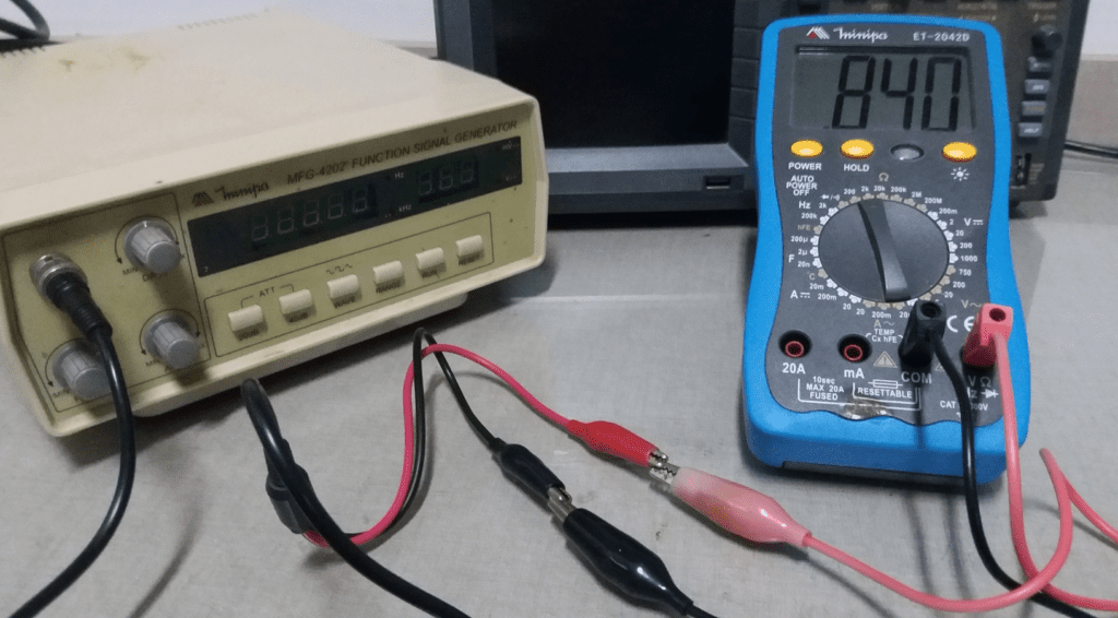
is the signal resistance. If input signal comes from a function generator, you can use a multimeter to connect with the probes of the turned down function generator and measure the resistance, which is 840 Ω.
To calculate .
R_{b1}||R_{b2}=\frac{R_{b1}\cdot R_{b2}}{R_{b1}+R_{b2}}=\frac{1500\cdot 220}{1500+220}=191.8\Omega
\beta \cdot r_{e}=171.94
R_{i}=\frac{191.8\cdot 171.94}{191.8+171.94}=90.66\Omega
The value of cutoff frequency f is 1 kHz, it was chosen arbitrarily. Calculating Ci.
1000=\frac{1}{2\pi (840+90.66)Ci}
The closest available commercial value is 100 nF. In this case, the cutoff frequency is 1.71 kHz. This is the formula to calculate Co.
Where , is the Thévenin resistance saw by output circuit without Co and
, which is the load resistance linked to Co. Since it won’t be linked to a load,
can be omitted and
. The chosen frequency was 20 kHz. Applying the equation above,
Co=79.5nF
Using the commercial value 100 nF, the frequency value is 15.91 kHz. The capacitor in parallel with serves to filter high frequency noises. The cutoff frequency formula:
If Ce is 1 μF, the cutoff frequency is 15.9 kHz.
A video demonstrating the operation of common emitter NPN amplifier. Due to input signal amplitude, the output signal saturates and reminds a square wave. Would have to increase Vcc or low the input signal amplitude.
Common emitter amplifier with PNP transistor

In this configuration, must work with negative values. The voltage supply (Vdc) is -9 V. The picked transistor is BC558.
Calculating collector resistor

The value of voltage gain A_{v} is also -100. On Q point, values are:
- Collector-emitter voltage: V_{CE}=-4.5V
- Base current: I_{B}=-150\mu A
- Collector current: I_{C}=-17mA
I_{E}=I_{B}+I_{C}=-0.15m-17m=-17.15mA
r_{e}=\frac{26m}{|I_{E}|}=\frac{26m}{17.15m}=1.51\Omega
A_{v}=-\frac{R_{C}}{r_{e}}
-100=-\frac{R_{C}}{1.51}
R_{C}=151\Omega
The commercial value is 150 Ω.
Calculating emitter resistor
Saturation current on Q point load line (I_{Csat}) is -37 mA.
I_{Csat}=\frac{V_{CC}}{R_{C}+R_{E}}
-37m=\frac{-9}{150+R_{E}}
R_{E}=94.6\Omega
The closest commercial value is 100 Ω.
Calculating resistors linked on the base
The gain β measured on BC558 is 236.
R_{b2}\leq \frac{\beta R_{E}}{10}
\frac{\beta R_{E}}{10}=\frac{236\cdot 100}{10}=2360
The chosen commercial value is 2200 Ω. Calculating voltage base V_{B}.
V_{E}=I_{E}\cdot R_{E}=-17.15m\cdot 100=-1.71V
Base-emitter voltage is -0.7 V.
V_{E}=V_{B}-V_{BE}
-1.71=V_{B}+0.7
V_{B}=-2.41V
V_{B}=\frac{R_{b2}V_{CC}}{R_{b1}+R_{b2}}
-2.41=\frac{2200(-9)}{R_{b1}+2200}
R_{b1}=6015.7\Omega
The closest commercial value is 5600 Ω.
Calculating capacitors
Calculating bypass capacitor Ce, parallel to R_{E}. The cutoff frequency was arbitrarily chosen as 30 kHz.
f=\frac{1}{2\pi R_{E}Ce}
Ce=\frac{1}{2\pi 100\cdot 30000}=53\cdot 10^{-9}F
The commercial value is 47 nF. Calculating input (Ci) and output (Co) capacitors.
\frac{R_{b1}R_{b2}}{R_{b1}+R_{b2}}=1582.05
\beta\cdot r_{e}=236\cdot 1,51=356.36
R_{i}=\frac{1582.05\cdot \beta\cdot r_{e}}{1582.05+\beta\cdot r_{e}}=290.84\Omega
R=R_{s}+R_{i}=840+290.84=1130.84\Omega
Choosing cutoff frequency f as 10 kHz.
f=\frac{1}{2\pi RCi}
Ci=\frac{1}{2\pi \cdot 1130.84\cdot 10^{4}}=140.7\cdot 10^{-9}F
Commercial value: Ci=100nF. Calculating Co with 30 kHz frequency.
f=\frac{1}{2\pi (R_{o}+R_{L})Co}
R_{o}=R_{C}=150\Omega
Co=\frac{1}{2\pi \cdot 150\cdot 30000}=35.37nF
Commercial value: Co=47nF.

The video of amplifier in operation. Must invert the supply poles.
In the next post about projects, I will show amplifiers in other configurations.