
The operational amplifier, or op-amp, has great utility on electronics. In this post, it’s shown the operation of this integrated circuit (IC).
Operation
It has two inputs, one inverting and another non-inverting and, an output.
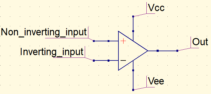
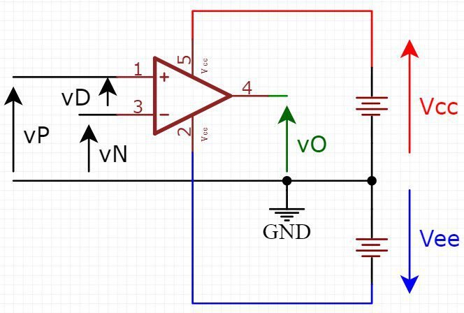
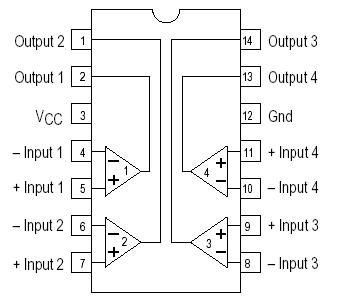
Op-amp can be supplied by a simple DC power source or a symmetric source. The latter type of source has three terminals: positive voltage, GND and negative voltage. To use a simple power source, Vee must be linked to GND. To supply op-amp with a symmetric power source, negative voltage terminal must be connected to Vee.
Ideal op-amp and virtual ground
An ideal op-amp would have an infinite input impedance, output impedance equal to zero, an infinite voltage gain in open loop and the component would be immune to temperature variations.

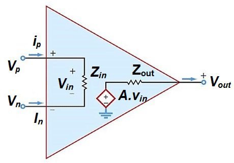
In an ideal operational amplifier, output impedance (Z_{out}) is zero, therefore:
V_{out}=A\cdot V_{in}
V_{in} is difference between the voltages V_{p} and V_{n}. Since voltage gain A is infinite,V_{in}=\frac{V_{out}}{A}=\frac{V_{out}}{\infty}=0
V_{in}=V_{p}-V_{n}
V_{p}=V_{n}
Virtual ground is useful to analyze circuits with op-amp, whose gain is too high. Allowing simpler calculations with good approximation.
The real operational amplifier
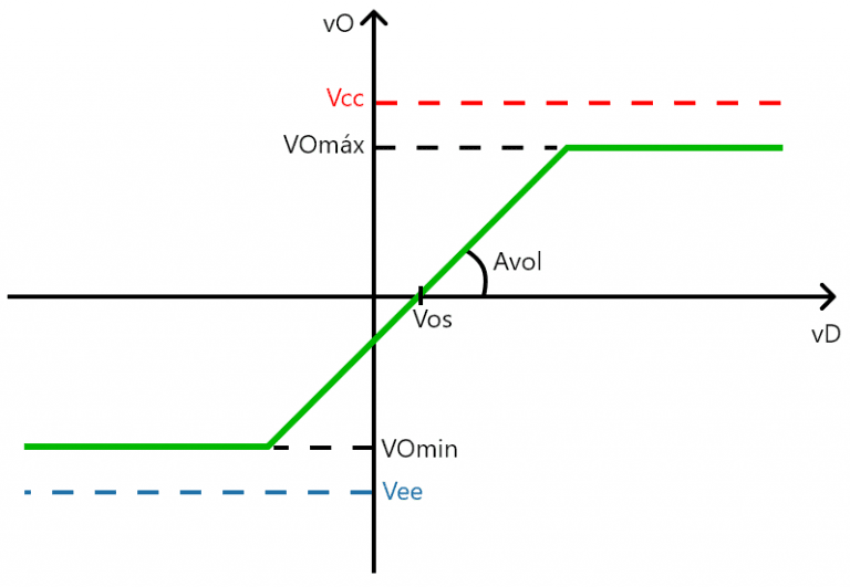
A real op-amp has a very high impedance, low output impedance, high open loop gain, however are limited. Also exists an offset voltage, which is a voltage value on output when input terminals are in short-circuit. Real amplifiers have slew rate (SR), which is the maximum rate of output voltage variation, measured in V/\mu s (voltages per microsecond).
Other important difference is the frequency range operation or band width. An ideal op-amp would have infinite band width, would operate in the same way in any frequency on input terminals. While the real has a limited frequency range, where it’s gain is constant and it’s decay when passes the limit of band width.

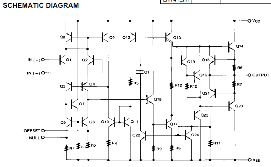
Inside operational amplifier
The op-amp is a complex circuit, formed by many transistors, resistors and other components.
Operational amplifier polarization
- Open loop: there’s no gain control and it’s used in comparator circuits.

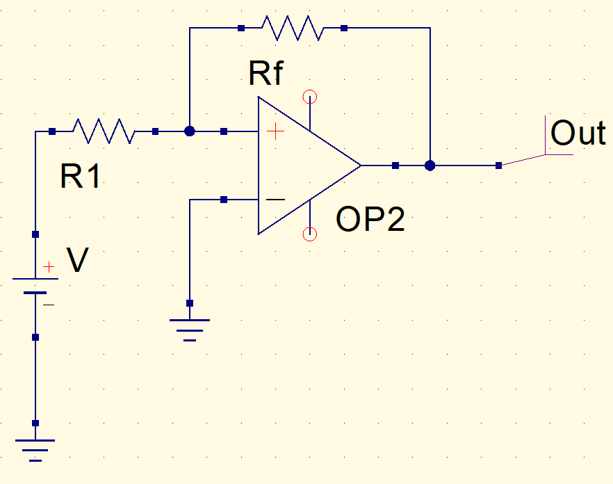
- Positive feedback: positive input is connected to the output. For being unstable, it’s used in oscillators.
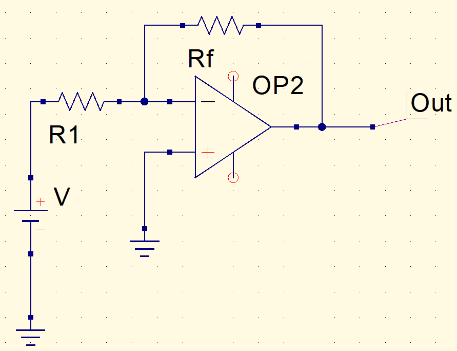
- Negative feedback: the most used polarization, serves for active filters, amplifiers, make mathematical operations, etc.
I will publish other posts about circuit analysis with op-amps and projects using this component.

.)