
This is the first part of a series of posts that show an analysis of practical circuits that use an operational amplifier (op-amp).
Post about the working principle of operational amplifier.Click here
In this post, op-amps will be considered as ideals.
Circuits with op-amp
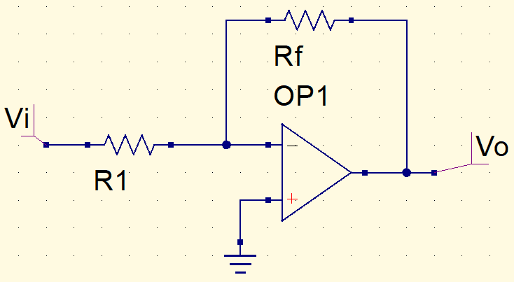
Inverter amplifier
Considering the op-amp circuit below.
This is the equivalent circuit.
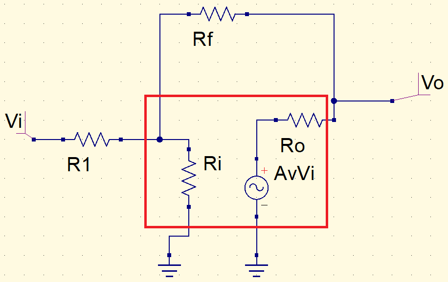
In an ideal op-amp, input impedance is infinite and output impedance is zero. Therefore, the equivalent circuit is,
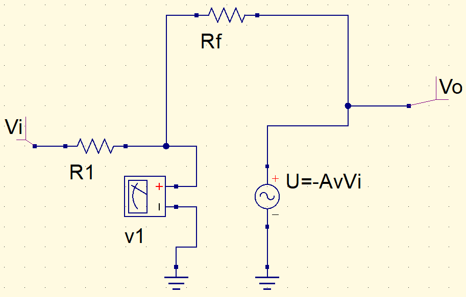
Applying the superposition theorem to find v1 voltage. Considering AvVi as zero.
v1_{1}=\frac{Rf}{R1+Rf}\cdot Vi
And Vi as zero.
v1_{2}=\frac{R1}{R1+Rf}\cdot(-AvVi)
v1=v1_{1}+v1_{2}=\frac{Rf}{R1+Rf}\cdot Vi+\frac{R1}{R1+Rf}\cdot(-AvVi)
v1=\frac{RfVi}{Rf+(1+Av)R1}
Usually, Av is much higher than 1 and AvR1 is much higher than Rf, therefore the equation becomes,
v1=\frac{RfVi}{AvR1}
The relation between output voltage and resistors.
\frac{Vo}{v1}=\frac{-Av\cdot v1}{v1}=-\frac{-AvRfVi}{v1AvR1}
This is the inverter amplifier output voltage equation.
V_{o}=-\frac{R_{f}}{R_{1}}\cdot V_{i}
Non-inverter amplifier
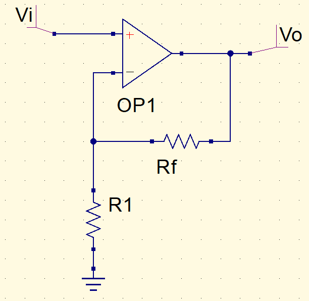
Using the voltage division equation, this result is reached.
V_{o}=\left (1+\frac{Rf}{R1}\right )\cdot V_{i}
Voltage buffer
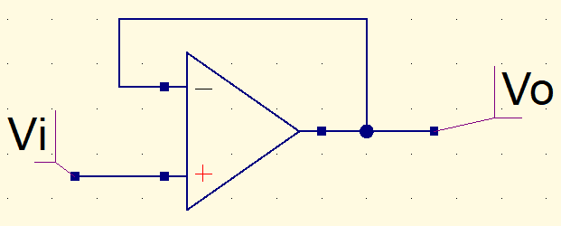
On a voltage buffer or unity amplifier, voltage output is equal to voltage input.
Amplifier adder
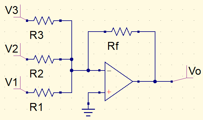
The equation is the sum of many inverters amplifiers.
V_{o}=-\left(\frac{Rf}{R1}\cdot V1+\frac{Rf}{R2}\cdot V2+\frac{Rf}{R3}\cdot V3\right)
Consider the circuit example below, which is an adder amplifier with commercial resistors, let’s calculate output voltage Vo.
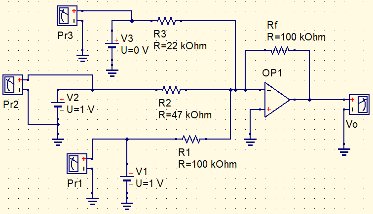
Applying the equation.
Vo=-\left(\frac{100k}{22k}\cdot 0+\frac{100k}{47k}\cdot 1+\frac{100k}{100k}\cdot 1\right)
Vo=-\left(2,12\cdot 1+1\cdot 1\right)=-3,13V
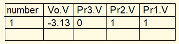
The result of circuit simulation.
Now, let’s make an adjustment on input voltages.

Applying again the same equation.
Vo=-\left(4,54\cdot 1+0+1\cdot 1\right)=-5,54V
And making the simulation.

What this example shows is that the adder can be used as a digital-analog converter (DAC). Input with R3 resistor is the most significative bit (MSB) and input with R1 is the least significative bit (LSB). In the first simulation, inputs were ‘011’, which generated close to 3V, since ‘011’ is 3 in binary. While on the second simulation, inputs were ‘101’, which is 5 in binary, and output was close to five.
Integrator

On inverter, if the feedback resistor is replaced by a capacitor, the circuit becomes an integrator. Considering virtual ground.
I=\frac{Vi}{R}=-\frac{Vo}{X_{C}}
X_{C} is capacitive reactance.X_{C}=\frac{1}{j\omega C}=\frac{1}{sC}
On Laplace notation, j\omega=s.
\frac{Vi}{R}=-\frac{Vo}{\frac{1}{sC}}=-sCVo
\frac{Vo}{Vi}=\frac{-1}{sCR}
Putting the equation on time domain.
v_{o}(t)=-\frac{1}{RC}\int v_{i}(t)dt
In input is a sine wave, output will be a sinusoid delayed 90º in relation to input.
Differentiator
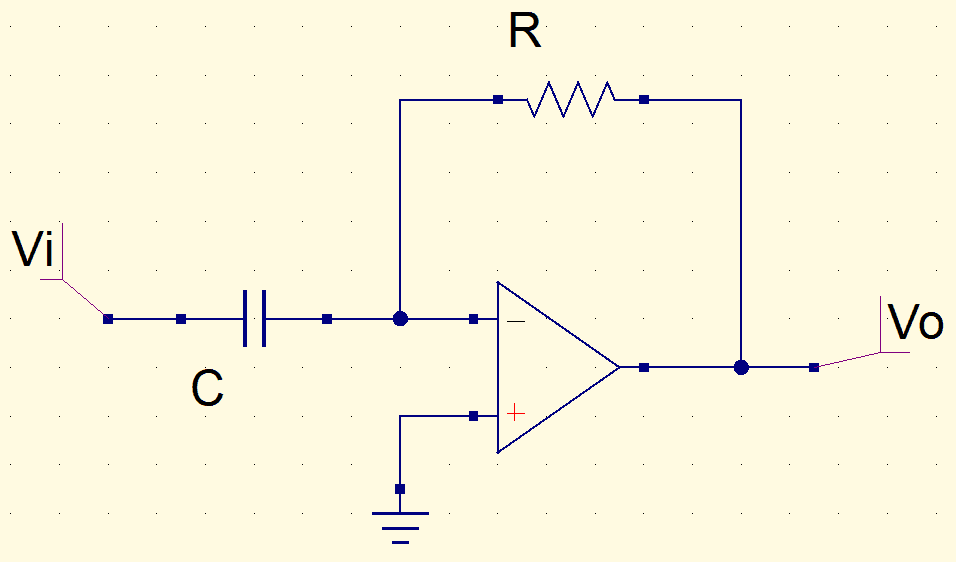
By switching positions of resistor and capacitor, we have the differentiator, which is the opposite of the integrator. Therefore, output signal is derivative of input signal. In this circuit, if the input is a sinusoid, the output will also be a sinusoid, but 90º early in relation to input. Below is the equation of output voltage on time domain.
v_{o}(t)=-RC\frac{dv_{i}(t)}{dt}


