
In this post, it’s shown how to use the PCA9685 module with Arduino. To control many servomotors this is a better solution than traditional commands.
Post about the operation of servomotorClick here
The board PCA9685
With a PCA9685, you can control until 16 servomotors connecting only two wires to Arduino, excluding supply wires.
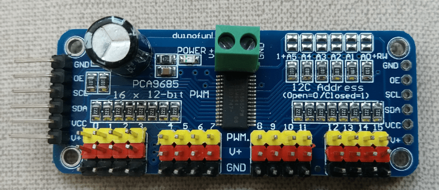
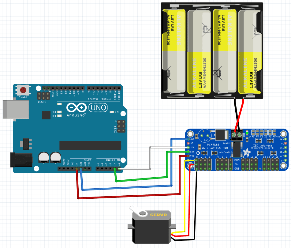
The PCA9685 communicates with Arduino through I²C communication protocol, it will be subject to a future post. The SDA pin must be linked to Analog 4 pin of Arduino Uno and SCL to Analog 5. To connect the motors, just observe that black, red, and yellow pins are GND, V+, and PWM respectively.
In other Arduino boards, the pinout for I²C protocol is different. Linking many boards in series can use a bigger quantity of servos. The theoretical maximum limit of PWM outputs is 992.

Energy source and voltage regulator
The Arduino’s 5 V supply is linked to Vcc. However, this 5 V is only for board’s chip. To supply the servos, it’s necessary an external supply source from 5 to 6 V. When higher the number of servomotors, a higher electric current is required. In this case, is recommended to use a voltage regulator.
The LM2596S

This is the adjustable regulator used in the present projects, LM2596S is a DC/DC step-down. By that, the output voltage is smaller than input, and both are direct. The specifications are:
- Input voltage: 3.2 to 40 V.
- Output voltage: 1.5 a 35 V.
- Maximum output current: 3 A.
- Efficiency: 92%.
- Maximum switching speed: 150 kHz.
The capacitor serves to avoid current peaks and filter noises. In this post, are shown two projects, one can be supplied directly by power source and another, where the regulator is mandatory.
Projects
It’s necessary to download the “Adafruit_PWMServoDriver.h” library, which is found in this link.
6 DOF robotic arm
This project controls the 6 DOF robotic arm shown in post “Unboxing of a robotic arm”, with PCA9685.
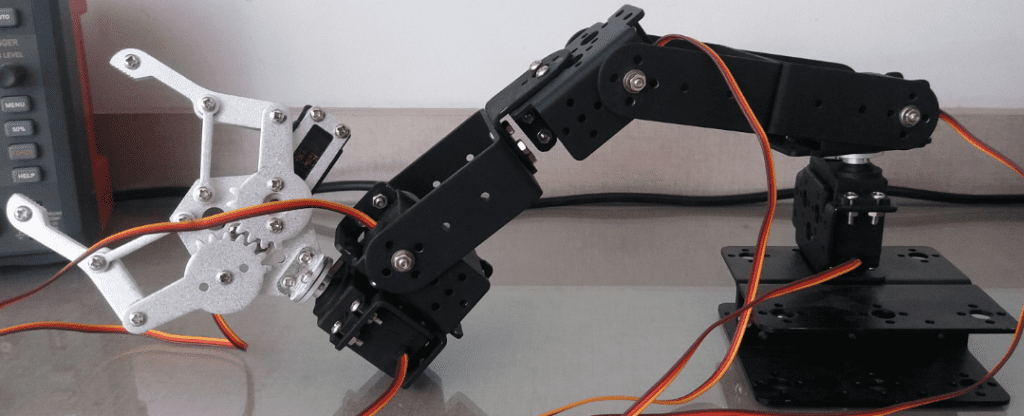
Assembling the robotic armClick here
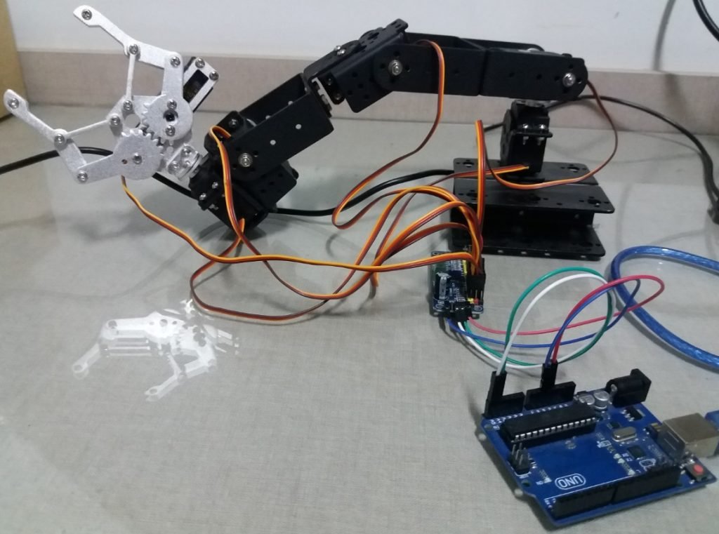
Connecting the robotic arm to PCA9685 and Arduino. Motors are linked from claw (terminal 1) to base (terminal 6).
This is the code with explanations in “//”.
#include <Wire.h> //Library which allows I2C communication.
#include <Adafruit_PWMServoDriver.h> //This library must be downloaded to run the code.

Adafruit_PWMServoDriver pwm = Adafruit_PWMServoDriver();//Instantiating objects with the Adafruit_PWMServoDriver class.

#define MIN_PULSE_WIDTH 650   //These are the minimum and maximum wavelength values which serve MG 995.
#define MAX_PULSE_WIDTH 2350
#define DEFAULT_PULSE_WIDTH 1500
#define FREQUENCY 60

int pulseWidth(int angle){ //This function calculates servo's motion angle.
int pulse_wide, analog_value;
pulse_wide = map(angle, 0, 180, MIN_PULSE_WIDTH, MAX_PULSE_WIDTH); //This function get angle from 0 to 180 degrees and map from length minimum value to maximum.
analog_value = int(float(pulse_wide) / 1000000 * FREQUENCY * 4096);
Serial.println(analog_value);
return analog_value; //The value this function returns.
}

void setup(){
Serial.begin(9600);
//Serial.println("16 channel Servo test!");
pwm.begin();  //Initialize the library and send PWM signals.
pwm.setPWMFreq(FREQUENCY); //Servo's update frequency at 60 Hertz.
pwm.setPWM(1,0,pulseWidth(0));
pwm.setPWM(2,0,pulseWidth(0));
pwm.setPWM(3,0,pulseWidth(0));
pwm.setPWM(4,0,pulseWidth(0));
pwm.setPWM(5,0,pulseWidth(0));
pwm.setPWM(6,0,pulseWidth(0));
}

void loop(){
pwm.setPWM(6,0,pulseWidth(45));
pwm.setPWM(4,0,pulseWidth(0));
delay(1000);
pwm.setPWM(3,0,pulseWidth(0));
pwm.setPWM(1,0,pulseWidth(120));
delay(500);
pwm.setPWM(3,0,pulseWidth(90));
pwm.setPWM(1,0,pulseWidth(0));
delay(2000);
delay(2000);
pwm.setPWM(2,0,pulseWidth(0));
pwm.setPWM(6,0,pulseWidth(0));
delay(2000);
}

//TESTING THE ARM.
//pwm.setPWM(1,0,pulseWidth(0)); //Open claw.
//pwm.setPWM(1,0,pulseWidth(120)); //Close claw.
//pwm.setPWM(2, 0, pulseWidth(90)); //Moving claw's position.

//pwm.setPWM(3,0,pulseWidth(20)); //Low number raise the hand.
//pwm.setPWM(3,0,pulseWidth(0)); //High number put down the hand.

//pwm.setPWM(4, 0, pulseWidth(180));//High number put down the elbow.
//pwm.setPWM(4, 0, pulseWidth(70));
In “pwm.setPWM” command, first number indicates the terminal where the servomotor is connected on board. While the second number controls PWM’s pulse length.
Servoclock
This project uses 12 micro servos, each one representing an hour in a clock, and a central motor as the second pointer. That’s why the name.
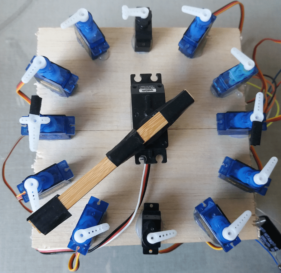
The central servomotor moves a step 60 times to give a single turn. After a complete turn, one of small servos does a small step. When the small servo makes 60 steps, it’s returns to original position and the next one, in clockwise moves. Have the option to make seconds pointer move faster.
Video of projects with PCA9685
The first part of video shows the servoclock, in this part the video was accelerated because it would take too long in normal speed. Second part is the robotic arm.
