
The two shown projects to make LED effect using the Johnson counter 4017.
Post that shows the operations of 4017 integrated circuit.Click here
4017 cascade
Material list:
- Printed Circuit Board (PCB).
- Wires: for LED support and link them to the board.
- 555.
- 4017.
- 1MΩ potentiometer.
- 74LS00.
- Resistors: a 220Ω, a 47kΩ and a 1kΩ.
- Electrolytic capacitors: a 10μF and a 1μF. The voltage limit for both must be at least 16V.
- LEDs: 9 reds and 8 yellows.
In this project, two 4017 chips are used to control 17 LEDs, with one, can control in maximum 10 LEDs. A 555 astable, whose frequency can be controlled by a potentiometer, makes a clock signal for 4017.

To put in cascade, it’s necessary an additional integrated circuit (IC) with logic doors.

To activate 17 LEDs, only two IC are used and a AND logic door. The second chip’s CE (pin 13) is linked to GND and Q9 is linked to pin 15 (reset) from first IC. The 74LS00 has 4 NAND logic doors. Using one of these as an inverter, it’s possible to obtain an equivalent AND logic.


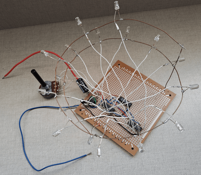
Electrical e-Library logo with LEDs
Material list:
- PCB.
- Wires.
- 555.
- 4017.
- 9V battery.
- Clip for battery.
- Electrolytic capacitors: a 2.2μF and a 10μF. The limit voltage must be 16V at minimum.
- Resistors: a 680Ω, a 470Ω, a 10kΩ, a 47kΩ and a 1kΩ.
- LEDs: 6 yellows and 10 whites.
- IRF640N.
This circuit’s operation is simpler, only a 555 astable, which generates a clock signal for a 4017, which turns on white LEDs in sequence. On 555’s pin 3, there’s a type N MOSFET that operates as switch to control yellow LEDs. The LEDs were arranged to form Electrical e-Library logo.

Video showing both circuits working.


