
I received requests to write more about capacitance and inductance. This post can be considered as the second part of derivated electrical quantities.
The first part of derivated electrical quantities is accessed in the following link.
Resistance, Capacitance, Inductance, Impedance and Reactance Click here
Physical explanation of capacitance
Considerate two conductors very close to each other, but they don’t touch. If a potential difference is applied in the conductors, one will be negatively charged, while the electrons from another will be repelled and it will be positively charged. Consequently, an electric field is created between the plates.

Eventually, electrons stop moving and there isn’t electric current anymore. This charging phase have already been shown in the post “RC circuit analysis“. The capacitor is discharged when there is no more voltage source and has a conductor way for electrons to move and make plates electrically neutral.
As the equations in first part shown, capacitance increases when the distance between the conductors is reduced. Increasing conductors’ area, increases the number of electrons in motion to load and unload the capacitor. Therefore, also increases the capacitance.
Why the capacitor does not allow sudden voltage change? Because potential difference in a capacitor depends on the number of charges in the plates. This is the current that passes through a capacitor.
i_{c}(t)=C\frac{dV}{dt}
Instant variation means dt=0, which requires an infinite current to move electrons instantly, which is impossible. The equation below, shown in the post about RC circuits, is an application of the equation above for RC step response.
i_{c}(t)=\frac{V_{o}}{R}e^{\frac{-t}{\tau}}
Dielectric material in the capacitor
All commercial capacitors have a dielectric material between the conductive plates, to increase the capacitance. The dielectric is an insulating material, but in presence of an electric field, it’s molecules align themselves with the field forming dipoles.

With the alignment of dielectric molecules, electrons of the negative plate are attracted by the positive side of polarized molecules. While electrons from positively charged plate are repelled by the negative side. Because of that, capacitance increases.

Physical explanation of inductance
As shown in the post “Introduction to electromagnetism“, the current by a conductor produces a magnetic field in the direction of right-hand law.
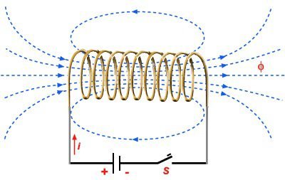
Why the inductor opposes current change? When the magnetic field changes in a conductor, it’s generated an induced current in this conductor. When current changes in an inductor, the magnetic field varies and consequently, an induced current is generated in this component. The induced current is in the opposite direction of the current that arrives in the coil. Lenz’s law says that an induced current produces a magnetic field in a direction that opposes the change of coil’s magnetic flux.

In permanent regime, coil acts like a short-circuit.
Capacitors and coils in AC
In alternate current, capacitors and inductors have capacitive and inductive reactances, respectively.
X_{c}=\frac{1}{\omega C}
X_{l}=\omega L
In high frequencies, the capacitor behaves like a short-circuit, while the inductor acts like an open circuit.
