In this post, are shown 2 circuit projects: an AC voltage detector and a cooler with LED effect.
AC detector

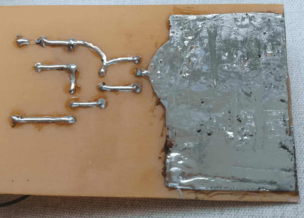
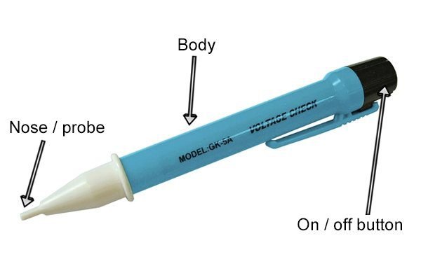
This sensor detects the alternate voltage (AC) without the need for connection with the circuit. Can be used to verify if there is a voltage on wires and outlets. The sensor is a conductive plate, that forms a capacitance (C1) with the wire. In addition to that, there are capacitances between the circuit and whoever is holding it (C2) and between the person and ground (C3). As alternate current passes through the wire, it’s formed a closed circuit.
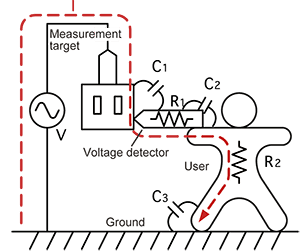
The plate is linked to the base of a BJT transistor. The current that passes through plate is very low. Therefore, are used 3 transistors in a Darlington configuration, so that the current is amplified enough to turn on LED and buzzer in the presence of AC. In the post about operation of BJT, it’s explained how the transistor amplifies base current.
How BJT transistor works?Click here
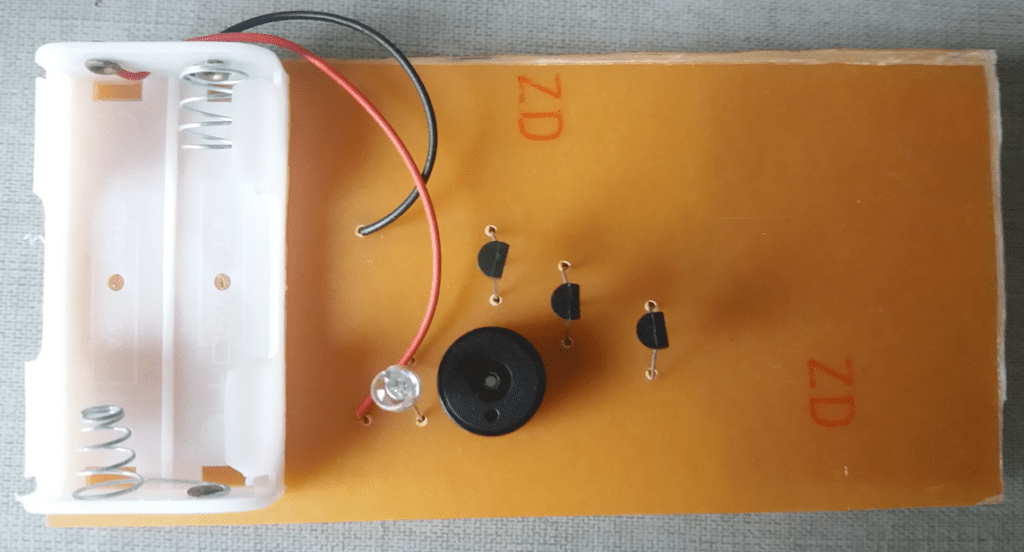
Component list:
- 3 BC548B transistors.
- 1 LED.
- 1 buzzer.
- 2 AA batteries.
- 1 support for 2 batteries.
- Printed circuit board.
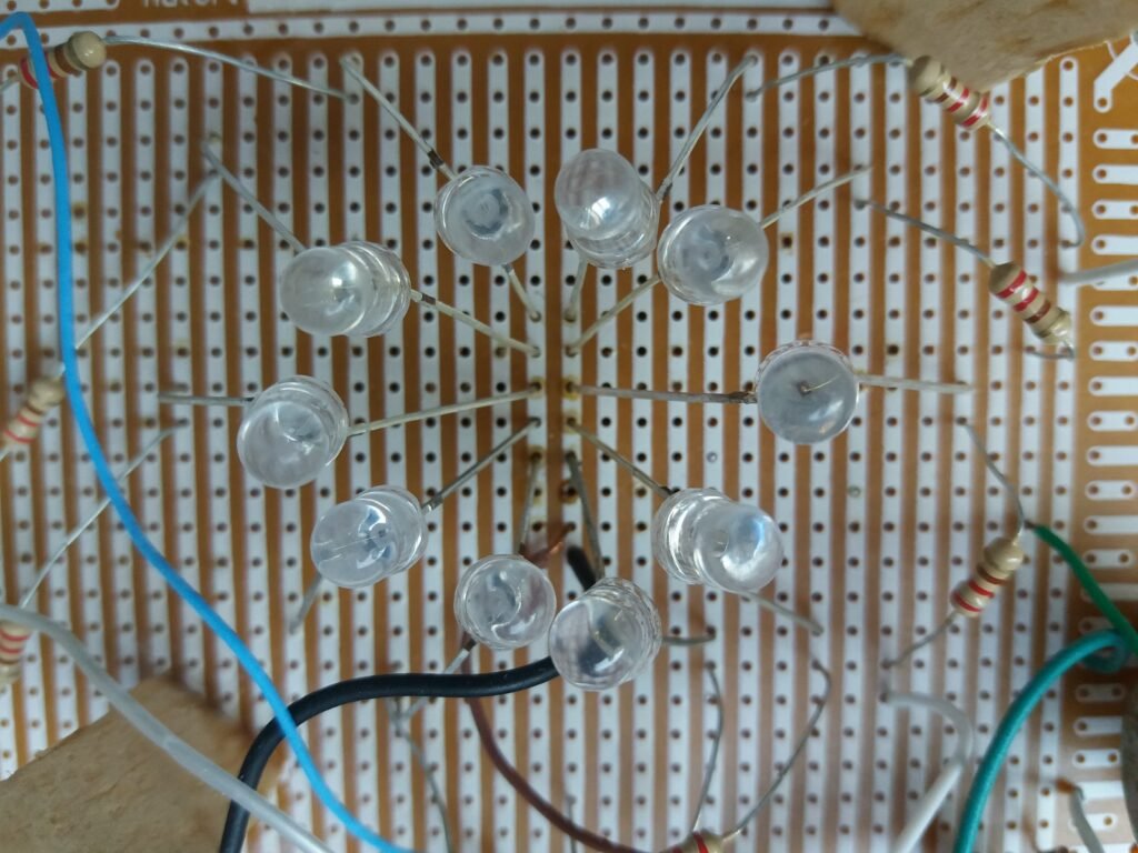
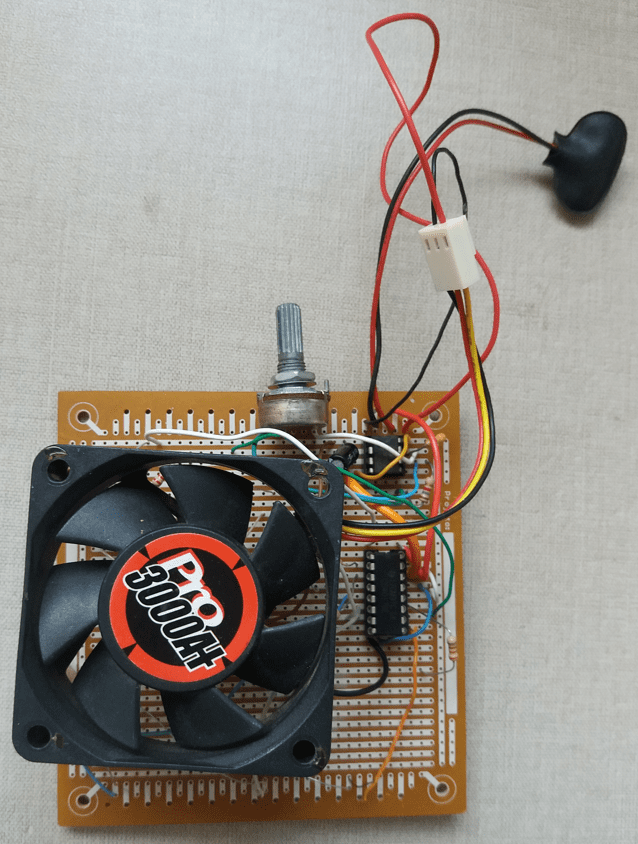
Cooler with LED effects

This circuit is an application of integrated circuits 555 and 4017. Their operations have already been explained in their respective posts. Where also are found pin descriptions of these chips.
This circuit is very similar to the LED chaser, shown in the post about 4017. The differences are: the cooler is connected in parallel to power source, different values for astable, and a potentiometer to change 555’s signal frequency, consequently, the speed of activation sequence.
The video below shows the operation of both circuits.