
This post shows how to design a sawtooth generator circuit, or ramp, which uses a current source and the integrated circuit 555.
The integrated circuit 555Click here
Sawtooth generator operation
Many different circuits generate a sawtooth waveform. A 6V direct voltage source (Vcc) supplies the oscillator.
Current source
First, must design a current source that charges the C1 capacitor. This source uses a PNP BJT transistor BC558, a potentiometer, and two resistors.

Current goes from 1mA to 12mA, whose intensity is controlled by the 1kΩ potentiometer RV1. If RV1 is adjusted to 0, the emitter voltage (V_{E}) will be 6V, therefore:
V_{BE}=V_{B}-V_{E}
-0.7=V_{B}-6
V_{B}=5.3V
Using voltage divider equation, to calculate the values of R1 and R2.
V_{B}=\frac{R2}{R1+R2}\cdot V_{CC}
R2 was arbitrarily chosen as 2.2kΩ.5.3=\frac{2200}{R1+2200}\cdot 6
R1=292.4\Omega
The commercial value of R1 can be 330Ω or 470Ω. C1 value determines sawtooth signal’s frequency, when higher the capacitance, lower the frequency.
Voltage sensor with 555

The C1 capacitor is connected to 555’s pin 2. The current source charges the capacitor until it reaches two-thirds of supply voltage (Vcc). When it with two-thirds of Vcc, the integrated circuit discharges the capacitor until it reaches one-third of Vcc and restarts the cycle.
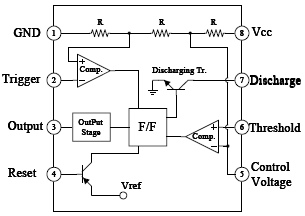
In this ramp generator, pins 2, 6, and 7 are linked. Pins 2 and 6 are comparators’ inputs (Comp.), to detect if the voltage on capacitor is on its limits. When voltage is on 2/3Vcc, pin 6 comparator sends a signal to the flip-flop (F/F), the latter’s output makes the transistor (Discharging Tr.) go into saturation and discharges the voltage to the ground. When the potential difference reaches one-third of Vcc, comparator linked to pin 2 sends a signal to F/F, to put the transistor in cut, to charge the capacitor and continue the cycle.


Below are the ramp generator’s output signals. Adjusting the potentiometer changes the frequency and duty cycle, which is the time that another signal’s half takes to reach the minimum voltage level.


The current source makes capacitor charge in a straight line, instead of a curve. The sawtooth generator is useful in PWM generation signals, audio synthesis, and cathodic tubes’ synchronization in oscilloscopes.
